Advertisement
Quick Links
COMMUNICATIONS - APPLIED TECHNOLOGY
Roger Bacon Drive
Reston, Virginia
1 1 2 5 0 - 1 4
2 0 1 9 0 - 5 2 0 2
800-229-3925 (voice)
703-471-4428 (fax)
http://www.c-at.com (internet)
Revision N
Setup and Operating Procedures
ICRI
TM
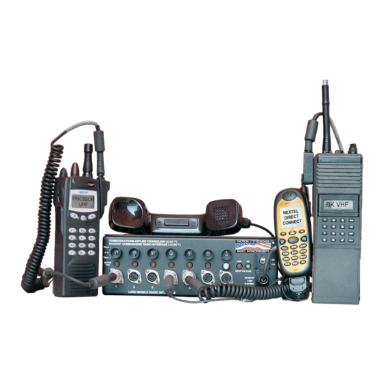
Incident Commanders' Radio Interface
TM
A Rapidly Deployable, Radio Interoperability Solution
Advertisement

Related Manuals for COMMUNICATIONS-APPLIED TECHNOLOGY ICRI

Summary of Contents for COMMUNICATIONS-APPLIED TECHNOLOGY ICRI
- Page 1 1 1 2 5 0 - 1 4 2 0 1 9 0 - 5 2 0 2 800-229-3925 (voice) 703-471-4428 (fax) http://www.c-at.com (internet) Revision N Setup and Operating Procedures ICRI Incident Commanders’ Radio Interface A Rapidly Deployable, Radio Interoperability Solution...
- Page 2 LAND MOBILE RADIO INTERFACE ......................9 FIGURE 14: RADIO WITH ICRI CABLE ATTATCHED ....................9 FIGURE 15: ICRI INTERFACE JACKS AND TALK GROUP SELECTOR ..............9 FIGURE 16: TWO RADIOS CONNECTED TO ICRI....................10 FIGURE 17: JACK ASSEMBLY (DRAWING) ....................... 11 TELEPHONE, CELLULAR PHONE AND HANDSET INTERFACE ...........13...
- Page 3 “trunked” radio systems] are keyed up). An ICRI contains up to six circuits that key the radios connected to the ICRI; these circuits are commonly referred to as “VOX” or “voice-activated switches.” The ICRI uses these circuits to perform other controlling functions as well.
- Page 4 The ICRI can be powered by the internal batteries or another DC source up to 20 VDC. The LEDs on the ICRI provide information battery status, in particular, a reliable indication of a low voltage condition.
- Page 5 FIGURE 1, counter-clockwise; be sure to close the purge valve after the pressure is released (turn clockwise) or the case will not be waterproof even with the lid latched. FIGURE 1: ICRI CASE (OUTSIDE) 1.2. The Pelican case will appear as in FIGURE 2 with radio interface cables located in the front recess.
- Page 6 1.4. A storage compartment for cables and batteries is located at the rear of the pouch. (The internal strap prevents the ICRI from falling through the open zippered compartment.) 1.5. Abbreviated set-up instructions are printed onto the top cover of the ICRI assembly. Connector information for radio, telephone, and power interconnect cables is printed on the bottom of the ICRI assembly.
- Page 7 ICRI POWER 2.1. To power the ICRI with the optional battery pack (8 “AA” cells), use the following instructions. FIGURE 5,FIGURE , FIGURE , FIGURE and FIGURE FIGURE 5: BATTERY INSTALLATION (DRAWING) The battery housing is comprised of two parts; the exterior case and an internal tray.
- Page 8 “locks” in place and the edges of the battery pack are aligned with the edges of the adaptor. FIGURE 9: BATTERY ATTACHMENT TO ICRI (VIEW 2) FIGURE 7: BATTERY ATTACHMENT TO ICRI (VIEW 1) - 5 -...
- Page 9 2.2. The ICRI maybe configured so that 8 “AA” batteries are installed inside the ICRI housing. The ICRI can also be powered by several forms of external power through a jack on the front panel of the ICRI. FIGURE 10: ICRI WITH INTERNAL BATTERIES 2.2.1.
- Page 10 2.3.1. When powering the ICRI with an alternate DC source or through a vehicle cigarette lighter jack, the cable assembly consists of three subassemblies: (A) the universal interconnect cable, (B) the cigarette lighter plug/ locking in-line jack and (C) the alligator clips/locking in-line jack.
- Page 11 2.4. Using an AC source to power the ICRI. 2.4.1. This power supply consists of two parts: (A) the three-prong AC power cable and (B) an AC to DC converter with an interconnect cable, FIGURE 13. Note: The AC supply must not be used where the cables or converter can become wet.
- Page 12 Interconnect cables provided by C-AT have a seven digit part number label on the cable. 3.1. Install the radio-end of the ICRI NOTE: The plug on the cable and the jack are interconnect cable onto the radio, as “keyed”.
- Page 13 FIGURE 16: TWO RADIOS CONNECTED TO ICRI - 10 -...
- Page 14 3.1.5. After the plug is fully seated on the jack, the locking ring on the plug should be turned clockwise until the ring cannot be turned further. FIGURE 17. FIGURE 17: JACK ASSEMBLY (DRAWING) 3.1.6. To remove the connector for cable storage, push inward on the locking ring and turn the ring counter clockwise to release the locking mechanism.
- Page 15 3.2.3.3. Center: no TG connection 3.3.3.2. Check to make sure the 3.2.4. Because the ICRI is connected to the cable is solidly connected to radio via the speaker jack, the audio the radio and the ICRI. path on the attached radio is disrupted.
- Page 16 FIGURE 20: ACOUSTIC COUPLER TO on its cable) and secure by stretching CELLULAR PHONE the elastic strap over the handset/cell phone. 4.1.6. Lastly, plug into ICRI at jack labeled “Telephone Interface (Coupler)”, 4.1.5. Position the RED pad directly over the FIGURE 22.
- Page 17 handset, a dial tone should be heard in the earphones of the portable radio and in the earpiece of the "local" handset. 4.1.10. Dial the telephone number of another telephone. FIGURE 22: TELEPHONE INTERFACE JACK 4.1.11. When the called party answers, use the portable radio's throat mic or a headset and begin to converse with called party.
- Page 18 25: CELLULAR PHONE release the locking mechanism. Then CONNECTOR (VIEW 2) pull the connector straight out of the 4.2.2. . Plug into ICRI at jack labeled jack. Hold the chrome barrel of the “Telephone Interface (Coupler)”, connector rather than the cable.
- Page 19 4.4. ICRI phone link in optional (RJ-10 connection) FIGURE 28: RJ-10 CABLE FOR NOKIA 4.4.1. The ICRI can be configured with an optional RJ-10 jack built into the unit. This jack will provide the user the ability connect a standard...
- Page 20 FIGURE 29: CONNECT TO NEXTEL DIRECT L-M-R. CONNECT 4.5.2. Install the radio-end of the ICRI 4.5.3. Attach the other end of the cable to any interconnect cable onto of the LAND MOBILE RADIO accessory jackat the bottom of the INTERFACE jacks.
- Page 21 ICRIs will permit interoperability of more than five radios, 5.2. FIGURE 5.2.1. Plug into ICRI at jack labeled “Telephone.” 5.2.2. FIGURE FIGURE 30: TWO LINKED ICRIs NOTE: The plug on the cable and the jack are “keyed”. Be sure to align the key before inserting the plug on to the connector or the connection may be damaged.
- Page 22 OPERATION OF THE ICRI 6.1.1. After connecting a power source to the ICRI (A), turn on the ICRI at (B) so that power up and input voltage can be verified. If you need to use a DC source voltage between 6.5 and 7.4 volts, then neither the OK (C) nor the LOW (D) voltage LEDs will be lit, but the ICRI...
- Page 23 This LED indicates the following: “Red” lit: input voltage 7.5 to 8.5 volts Note: If neither is lit, the ICRI will operate on voltage as low as 6.5V Maximum input voltage is 20VDC 6.2.5. RADIO INTERFACE JACK (1 thru 5)
- Page 24 6.2.6. TELEPHONE INTERFACE JACK: This 8-pin locking-type jack supports the connection of the ICRI to a telephone through the acoustic coupler (PN 1790.650) or the 2.5mm jack on a cell phone (PN 179.0672) Pinout: 1- Audio TO telephone (acoustic coupler)
- Page 25 500.9280 TWO TALK GROUP SELECTION RACK MOUNTABLE ICRI ICRI, 5 radio + 1 handset + 1 telephone I/O port in 19", 2 U high, rack mount configuration. TWO TALK 500.9261 GROUP SELECTION FOR PORTS ICRI, 10 radio + 1 handset + 1 telephone I/O port in 19", 2 U high, rack mount configuration (includes 500.9265...
- Page 26 MT-1000, HT-600, HT-2000, MT-300, MTX-800, MTX-820S, MTX-900 & Radius P- 179.0640 200 interface cable Motorola Spectra interface cable ("Y" cable/box so normal function of radio is not affected by ICRI 179.0636 link) Motorola MCS-2000 interface cable ("Y" cable/box so normal function of radio is not affected by ICRI 179.0635...
- Page 27 NOTE: TO REMOVE THE CONNECTOR, PULL ON THE BACK OF THE CONNECTOR BODY INSTEAD OF TWISTING OR TURNING THE CONNECTOR. 3. TURN ON THE ICRI. THE RED OR GREEN LIGHT BELOW THE POWER SWITCH SHOULD BE LIT. NOTE: IF NEITHER LIGHT IS LIT, VERIFY THAT THE POWER SOURCE IS PROPERLY CONNECTED AT BOTH ENDS.
- Page 28 6-REQUIRED JUMPER 4- SABER P-T-T ONLY 3-8 - N/C 3-PTT 2-AUDIO FROM RADIO 5-SHIELD GND 4-AUDIO HI+ 5-P-T-T 5-AUDIO HI- 3-AUDIO TO RADIO 4 -FROM PHONE 5-SHIELD GND 2 -FROM PHONE FIGURE 35: BOTTOM OF ICRI CHASSIS - 25 -...
- Page 29 APPENDIX D: Pictorials of Applications ICRI ALTERNATE APPLICATIONS BELOW GRADE OR IN-BUILDING LINK TO TRUNKED REPEATER REPEATER UP TO 1,000' INTERFACE CABLE TRUNKED CHANNEL 1st RESPONDER TALK AROUND CHANNEL LINK REPEATING BODY WIRE SIGNAL TAPE RECORDER MOBILE VEHICLE-MOUNT RADIO BODY WIRE...
- Page 30 ICRI WITH ATTACHMENTS (NOTE: NOT TO SCALE) (+) RED ALLIGATOR CLIPS (-) BLACK CIGARETTE LIGHTER 8 "AA" BATTERY PACK UP TO 1,000' INTERFACE CABLE PORTS ARE NOT RADIO SPECIFIC INTERCONNECT CABLE TECHNICAL NOTES ON BOTTOM SIDE. (PORTABLE OR MOBILE RADIO CAN BE USED.) USER INSTRUCTIONS ON TOP COVER.
- Page 31 APPENDIX E: Pictorials of Board Adjustments - 28 -...
- Page 32 - 29 -...
- Page 33 APPENDIX F: Connecting External Speakers (Optional not standard) Connecting the ICRI to external speakers via the optional speaker assembly and cables permits the user to continuously monitor all radio traffic crossing the ICRI. The two separate speaker jacks allow the user to monitor both talk groups simultaneously. FIGURE 36.
- Page 34 FIGURE 38: ICRI CONNECTED TO AMPLIFIED SPEAKERS § 15.21 Information to User: Caution! Change or modification not expressly approved by the party Communications-Applied Technology could void the user’s authority to operate the equipment. §15.105(b) Information to User: NOTE: This equipment has been tested and found to comply with the limits for a Class B digital device, pursuant to part 15 of the FCC Rules.
- Page 35 ICRI. See Figure X The extension cable is inserted between the ICRI and the radio interconnect cable, that is usually connected directly to one of the radio ports on the ICRI front panel. See Figures Y and Z. Figure XXXX...
- Page 36 Be sure to align the keyway and secure the connectors together with the locking ring on the male connector. Connect the unspooled cable to a radio port on the ICRI. Be sure to align the keyway and secure the connectors together with the locking ring on the male connector.
Need help?
Do you have a question about the ICRI and is the answer not in the manual?
Questions and answers