Table of Contents
Advertisement
Quick Links
USER NOTICE M210
Important note
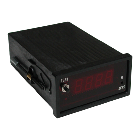
The M210 device is an electronic which puts forward its analogue output before its display (the display works as an
output copy). All metrological check has to be done thru the analogue output.
1. Before you start
• Connect the sensor to the conditioning module as per the wiring scheme.
• Ensure that the wires are correctly tightened into the terminal block.
• Connect the M210 to the 230 Vac – 50Hz supply or DC supply (depending on version).
• Wait a few moments for the display to stabilise (warm-up time).
NOTE:
The standard M210 can function with 115 V – 50 Hz (main supplied version) by changing an internal
jumper.
TE CONNECTIVITY SENSORS
/// USER NOTICE M210_EN
03/2018
Page 1
Advertisement
Table of Contents

Summary of Contents for TE Connectivity M210
- Page 1 USER NOTICE M210 Important note The M210 device is an electronic which puts forward its analogue output before its display (the display works as an output copy). All metrological check has to be done thru the analogue output. 1. Before you start •...
-
Page 2: Analogue Output
USER NOTICE M210 2. Analogue output 2.1 SETTING THE ZERO • Use the front panel potentiometer (bottom right hand side) to set the output to 0 Vdc. 2.2 SETTING THE GAIN • The gain is set using the calibration function and the gain potentiometer. The gain potentiometer is hidden behind the front panel on the bottom right hand side, above the zero potentiometer. - Page 3 "ADJUSTMENT" section if no pushbutton is present). • Use the gain potentiometer to obtain the calibration value on the display. • Release the pushbutton, check the zero and refine the adjustments if necessary. The M210 is ready to function TE CONNECTIVITY SENSORS /// USER NOTICE M210_EN...
-
Page 4: Sensor Excitation
USER NOTICE M210 TECHNICAL DATA SHEET M210 1 Supply • Main: 230 or 115 V (± 10%) / 50 to 60 Hz; (6 VA). Internal jumper S1: A = 115 V and B = 230V. • DC versions: M210/12: 10 to 18 V / 0.5 A. - Page 5 USER NOTICE M210 3 Sensors signal amplification • Gain: from 10 to 1000 (resistance). • Input impedance: 100 k. • Stability: 1V /°C (typ.) closed loop 4 Analogue output (A.O.) • Amplitude: ± 10 Vdc / 5 mA (short-circuit protected).
-
Page 6: Short Circuit
USER NOTICE M210 Decimal point position on the display To define the decimal point position on the display, points 1, 2 or 3 on the left of the display are connected with a solder point (see the drawing below). Short-circuit : None for "1999"... - Page 7 USER NOTICE M210 ADJUSTMENT M210 I. RG1 gain resistance calculation for ±10 V output The position of the RG1 gain resistor is shown in the schema included in this document. RG1 GAIN RESISTANCE CALCULATION FORMULA: ...
- Page 8 USER NOTICE M210 II. Calibration resistance RC1 The positions of the RC1 calibration resistor and BP are shown in the schema included in this document. RC1 RESISTANCE DETERMINATION • Short-circuit BP, and put a variable resistance (decade box) in place of RC1.
- Page 9 USER NOTICE M210 CONNECTIONS M210 • 3 PIN TERMINAL "SUPPLY" Earth Phase or –V = Phase or +V = • 10 PIN TERMINAL "MEASUREMENT" Sensor shield - Current output (Option I) - Sensor signal + Current output (Option I) + Sensor signal...
- Page 10 USER NOTICE M210 TE CONNECTIVITY SENSORS /// USER NOTICE M210_EN 03/2018 Page 10...
- Page 11 AL2 = High threshold (HT) and Low threshold (LT). A. Adjustments • Adjustments are carried out once the M210 standard set up has been accomplished. • The threshold values are set using the pushbuttons and potentiometers in the upper corners of the front panels.
- Page 12 USER NOTICE M210 C. Six pin connector wiring scheme Common LT Common HT Rest LT Rest HT Work LT Work HT Rear Panel THRESHOLDS MEASUREMENT SUPPLY Front Panel Note: SH = High Threshold; SB = Low Threshold TE CONNECTIVITY SENSORS...
- Page 13 TE Connectivity‘s obligations shall only be as set forth in TE Connectivity‘s Standard Terms and Conditions of Sale for this product and in no case will TE Connectivity be liable for any incidental, indirect or consequential damages arising out of the sale, resale, use or misuse of the product.

Need help?
Do you have a question about the M210 and is the answer not in the manual?
Questions and answers