
Related Manuals for Orisec INT-CS

Summary of Contents for Orisec INT-CS
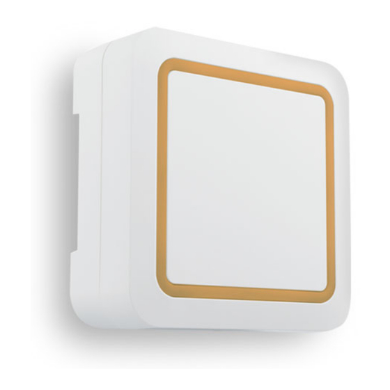
- Page 1 INT-CS Internal Compact Sounder Installation Instructions Designed and Manufactured in the United Kingdom www.orisec.co.uk...
- Page 2 Introduction The INT-CS Internal Sounder provides 5 programmable high-level alarm sounds along with a long-life strobe. It can also provide low-level notification tones, for example entry/exit, chime, warning etc, with multi-coloured LED status indication. Features • Orisec Network Compatible • Piezo (High-Level) for Alarm Sounds •...
- Page 3 Mounting the INT-CS To open the internal sounder loosen the locking screw by turning anti-clockwise, then hinge the front cover up and away from the backplate. Loosen Screw Piezo Plug Piezo Lead...
- Page 4 Four screw fixing holes and eight cable entry locations are provided to aid mounting. Conduit Entry Wall Tamper Wall Tamper PCB Screw I/01 I/02 +12V...
- Page 5 Bringing the Cable in Remove the PCB by unscrewing the two screws. Bring the cable into the housing through one Loose of the cable entry points. Then feed the cable through the slot in the PCB as shown below. Connect the lead from the piezo to the piezo plug. Piezo Plug Piezo Lead...
- Page 6 High Voltage Area (when product is sounding) Network Connection Conventional Connection The INT-CS can operate as a simple conventional sounder and For full functionality connect the INT-CS to the LED 1 LED 2 strobe when connected to other manufacturers’ control panels.
- Page 7 Optional W-AP An optional wireless access point W-AP is available separately. The W-AP can be used for: • Wireless Activation of the INT-CS • Wireless Repeater Functionality NOTE: Do not add/ remove the W-AP whilst the INT-CS is powered.
- Page 8 6. Press and hold “Learn” button for 1-2 seconds Once the INT-CS has been learned to the control panel the unit will automatically operate as a wireless repeater. Products that can act as repeaters cannot themselves be repeated. For a full list of products that can be repeated please see this link: www.orisec.co.uk/compatible-products...
-
Page 9: Program Options
Sound Generated When BELL is Triggered Sound 1 Sound 2 Sound 3 Sound 4 Sound 5 Light Ring On Time 10 sec 30 sec 60 sec Light Ring Colour When Bell Is Triggered Green Blue Pink Orange White Orisec Blue Bold indicates default settings... -
Page 10: Specifications
Specifications Electrical Supply Voltage: 9 - 16 VDC (13.7 V nominal) Current Consumption: Idle: 20mA at 9.0V, 28mA at 16.0V Strobe: 20mA Siren: 300mA at 9.0V, 190mA at 16.0V Network: 4-wire standard 7/0.2 alarm cable up to 500m. I/O Channels: 2;... -
Page 11: Warranty
Manufacturer: Orisec Ltd, 1 St Crispin Way, Haslingden, Lancashire. BB4 4PW. United Kingdom. Warranty The INT-CS is guaranteed against defects in material or faulty workmanship for a period of 2 years from the date of purchase. Disclaimer: Orisec will not accept any liability based on a claim that the INT-CS failed to perform correctly as it is a component part of an installation and not a complete intruder alarm system. - Page 12 UK Based Technical Support: t: +44 (0) 1706 398740 © Copyright Orisec Ltd 2021 e: support@orisec.co.uk INS128...
Need help?
Do you have a question about the INT-CS and is the answer not in the manual?
Questions and answers