Table of Contents
Advertisement
Quick Links
Advertisement
Table of Contents

Related Manuals for opto engineering COE LS-X Series


Summary of Contents for opto engineering COE LS-X Series
- Page 1 USER MANUAL Line Scan Camera COE LS-X Line Scan Camera V 1.0 - eng CAMERAS...
- Page 2 COE LS-X Line Scan Camera | USER MANUAL Legal Information About This Manual This manual is applicable to the COE LS-X line scan cameras. The Manual includes instructions for using and managing the Product. Pictures, charts, images and all other information hereinafter are for description and explanation only. The information contained in the Manual is subject to change, without notice, due to firmware updates or other reasons.
- Page 3 COE LS-X Line Scan Camera | USER MANUAL Regulatory Information EU Conformity Statement This product and - if applicable - the supplied accessories too are marked with "CE" and comply therefore with the applicable harmonized European standards listed under the EMC Directive 2014/30/EU, the LVD Directive 2014/35/EU, the RoHS Directive 2011/65/EU.
- Page 4 COE LS-X Line Scan Camera | USER MANUAL ⚫ Avoid contact with exposed circuit. When the device is powered on, avoid contact with exposed junctions and parts. ⚫ Use the power adapter provided by the regular manufacturer. ⚫ Do not connect multiple devices to one power adapter, to avoid over-heating or fire hazards caused by overload.
- Page 5 COE LS-X Line Scan Camera | USER MANUAL disassemble the device arbitrarily. Cleaning Do not touch the image sensor directly. If the sensor needs to be cleaned, use a clean rag and wet it with alcohol, then gently wipe off the dirt; if the device is not in use, cover the image sensor with dust cover for protection.
-
Page 6: Table Of Contents
COE LS-X Line Scan Camera | USER MANUAL INDEX 1 Overview ....................9 1.1 Introduction ........................9 1.2 Key Feature ........................9 2 Appearance ..................... 10 3 Interface and Indicator ................11 3.1 Power and I/O Interface ....................11 3.1.1 First Type of Pin Definitions ......Errore. Il segnalibro non è definito. 3.1.2 Second Type of Pin Definitions ....... - Page 7 COE LS-X Line Scan Camera | USER MANUAL 7.6.2 Trigger Activation ....................34 7.6.3 Trigger Delay ......................36 7.6.4 Frame/Line Trigger Cache ..................37 7.6.5 Trigger Debouncer ....................39 8 I/O Output ....................41 8.1 Select Output Signal ..................... 41 8.2 Set Output Signal ......................
- Page 8 COE LS-X Line Scan Camera | USER MANUAL 10.18 Set Saturation ......................75 10.19 Set Color Adjustment ....................75 10.20 Set LUT ........................76 10.21 Set Flat Field Correction ................... 77 10.21.1 FPNC Correction ....................77 10.21.2 PRNUC Correction ................... 78 10.22 Set Space Correction ....................
-
Page 9: Overview
COE LS-X Line Scan Camera | USER MANUAL 1 Overview 1.1 Introduction The COE LS-X line scan camera uses the GigE interface to transmit images in real time, and it acquires images and sets parameters via the client software or SDK. The camera is applicable to the printing, textiles, railway, logistics, metallurgy, food, pharmaceutical manufacturing, material sorting, etc. -
Page 10: Appearance
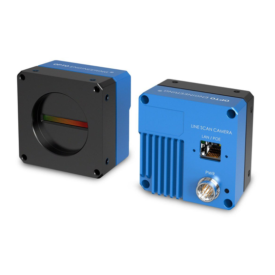
COE LS-X Line Scan Camera | USER MANUAL 2 Appearance Appearances here are for reference only. Refer to the camera's specification for detailed dimension information and corresponding models. Dimensional drawings Figure 1-1 Table 1-1 Component Description Name Description Lens Mount It is used to install the lens. -
Page 11: Interface And Indicator
COE LS-X Line Scan Camera | USER MANUAL 3 Interface and Indicator 3.1 Power and I/O Interface All COE LS-X cameras have the same 12-pin power and I/O interface, as shown below. 12-Pin Interface Figure 1-2 Refer to the pin definitions and labels attached to the power and I/O cable to wire the device. Table 1-2 Pin Definitions I/O Signal Signal... - Page 12 COE LS-X Line Scan Camera | USER MANUAL The camera indicator is used to display camera status. Table 1-3 Indicator Description No. Indicator Color Status Description Flashing very Cable connection error occurs. slowly Solid Major error occurs. Blue Flashing slowly The camera is acquiring images under trigger mode.
-
Page 13: Camera Installation
COE LS-X Line Scan Camera | USER MANUAL 4 Camera Installation 4.1 Installation Preparation You need to prepare following accessories before installation. Table 1-4 Accessories Name Quantity Description Lens You should purchase lens separately according to the camera’s lens mount. Lens Adapter You should purchase lens adapter separately according to the camera’s lens mount and lens you... -
Page 14: Install Client Software
COE LS-X Line Scan Camera | USER MANUAL 5.1 Install Client Software OECS client software is used to connect the camera, set its parameters, etc. ⚫ The OECS client software is compatible with 32/64-bit Windows XP/7/10 operating systems. ⚫ The graphic user interface may differ by different versions of the client software you use. ⚫... -
Page 15: Turn Off Firewall
COE LS-X Line Scan Camera | USER MANUAL Finish the installation according to the interface prompts. 5.2 Turn off Firewall To ensure stable client running and image transmission, you are recommended turning off Windows firewall before using the client software. For different Windows versions, the path name or interface may differ. -
Page 16: Set Camera Network
COE LS-X Line Scan Camera | USER MANUAL Set NIC property via the PC. 1) Go to NIC settings page: Control Panel > Hardware and Sound > Device Manager > Network Adapter. 2) Select corresponding network interface card, and click Advanced. 3) Set Jumbo Packet value to 9014 Bytes, Transmit Buffers and Receive Buffers to 2048, Interrupt Moderation Rate to Extreme. - Page 17 COE LS-X Line Scan Camera | USER MANUAL Double click the device name in device list, or click to connect the device to the client. V 1.0 - eng...
-
Page 18: Client Software Layout
COE LS-X Line Scan Camera | USER MANUAL 6 Client Software Layout After connecting to the camera, the client software can read the camera attributes and display them. Main Window Figure 1-7 For specific main window of the client software, please refer to the actual one you got. Table 1-5 Description of Main Window Area Name Description... - Page 19 COE LS-X Line Scan Camera | USER MANUAL The camera’s attribute tree and parameters may differ by camera models. Table 1-6 Attribute Description Attribute Description You can view device information, edit its name, reset the device, Device Control etc. You can view and set the device resolution, image reverse function, Image Format Control pixel format, region of interest, test pattern, etc.
-
Page 20: Image Acquisition
COE LS-X Line Scan Camera | USER MANUAL 7 Image Acquisition 7.1 Set Line Rate Line rate refers to the image line number that is output by the camera per second. The frame rate of the camera is proportional to the line rate, and is inversely proportional to the height of the image area, that is, Fps = Lps (line rate)/Height (image height). -
Page 21: Set Frame Timeout
COE LS-X Line Scan Camera | USER MANUAL View Reference Line Rate Figure 1-9 ⚫ After enabling the image compression mode, the camera line rate and frame rate are related with exposure and camera sensor only. 7.2 Set Frame Timeout ⚫... -
Page 22: Set Acquisition Mode
COE LS-X Line Scan Camera | USER MANUAL Enable or disable Partial Frame Discard and Abandon Extra Image according to the desired value. Set Frame Timeout Figure 1-10 7.3 Set Acquisition Mode The camera has 2 acquisition modes, including SingleFrame mode and Continuous mode. ⚫... -
Page 23: Set Trigger Source
COE LS-X Line Scan Camera | USER MANUAL Trigger Parameter Parameter Value Description Mode and Trigger Mode Trigger Selector =Frame Burst Start Trigger Mode =Off Trigger Selector =Line Start Acquisition Under this mode, the frequency of the Trigger Mode = On Control >... -
Page 24: Set Software Trigger
COE LS-X Line Scan Camera | USER MANUAL The software trigger and action command trigger are valid for the frame trigger only, and the shaft encoder control is valid for the line trigger only. Table 1-9 External Trigger Mode Principle and Parameter Trigger Parameter Parameter... -
Page 25: Set Hardware Trigger
COE LS-X Line Scan Camera | USER MANUAL Click Acquisition Control > Trigger Selector. Select Frame Burst Start as Trigger Selector, and On as Trigger Mode. Select Software as Trigger Source, and click Execute in Trigger Software to send trigger commands. -
Page 26: Set Shaft Encoder Control
COE LS-X Line Scan Camera | USER MANUAL When selecting bi-directional configurable line as the hardware trigger source, you need to make sure that its line mode is input. Go to Digital IO Control, select specific line as Line Selector, and Input as Line Mode. - Page 27 COE LS-X Line Scan Camera | USER MANUAL Function Demonstration Figure 1-15 The advantages of shaft encoder are as follows: ⚫ Encoder output pulse frequency is proportional to rotating speed. ⚫ The output pulse acts as a trigger signal for line scan camera. ⚫...
- Page 28 COE LS-X Line Scan Camera | USER MANUAL Process Logic of 2 Ticks Figure 1-17 Process Logic of 4 Ticks Figure 1-18 Encoder Trigger Frequency outputs 4 signals by default. Set Encoder Counter Mode. ⚫ Ignore Direction means that both forward and backward direction will count. ⚫...
-
Page 29: Set Frequency Converter Control
COE LS-X Line Scan Camera | USER MANUAL After reaching the max. value, it will be cleared automatically or you can clear manually by clicking Encoder Counter Reset. (Optional) Set Encoder Max Reverse Counter to avoid outputting images if the object moves backward accidently during measurement, and click Execute in Encoder Reverse Counter Reset to let the camera to output images again. -
Page 30: View Trigger Line Rate
COE LS-X Line Scan Camera | USER MANUAL Set Frequency Converter Control Figure 1-21 7.5.5 View Trigger Line Rate ⚫ Trigger Line Rate: It relates to the external trigger raw line rate after filtering, and it only involves external trigger signals. ⚫... -
Page 31: Set Action Command Trigger
COE LS-X Line Scan Camera | USER MANUAL 7.5.6 Set Action Command Trigger The action command allows you to execute actions on multiple cameras at roughly the same time by using a single broadcast protocol message. ⚫ The action command function is available only with client software version of V3.1.0 and higher. -
Page 32: Set Free Trigger
COE LS-X Line Scan Camera | USER MANUAL operation of the Group Mask against the Action Group Mask feature should result in non- zero. Enable Scheduled. Click in Benchmark Camera to select one camera as benchmark camera. Once benchmark camera is selected, other cameras keep time synchronization with it. (Optional) Enter Delay Time according to actual demands. -
Page 33: Trigger Related Parameters
COE LS-X Line Scan Camera | USER MANUAL 7.6 Trigger Related Parameters If the camera enables the frame trigger or line trigger, you can set trigger related parameters, including acquisition burst frame count, trigger activation, trigger delay, trigger cache, and trigger debouncer. -
Page 34: Trigger Activation
COE LS-X Line Scan Camera | USER MANUAL Set Burst Frame Count Figure 1-25 When Acquisition Burst Frame Count is 1, it is in single frame trigger mode. When Acquisition Burst Frame Count is larger than 1, it is in multi-frame trigger mode. If Acquisition Burst Frame Count is n and when inputting 1 trigger signal, the camera stops acquiring images after exposing n times and outputs n frame images. - Page 35 COE LS-X Line Scan Camera | USER MANUAL Trigger Parameter Parameter Description Activation Value Level High Acquisition Control > Level High The camera triggers only when the Trigger Activation level signal sent by the external device is in the level high. Level Low Acquisition Control >...
-
Page 36: Trigger Delay
COE LS-X Line Scan Camera | USER MANUAL Level Trigger in Frame Trigger Figure 1-28 ⚫ Set Trigger Activation in Line Trigger In the line trigger mode, the trigger activation is related with Exposure Mode. ⚫ When Timed is selected as Exposure Mode, you can select Rising Edge or Falling Edge as Trigger Activation, and Exposure Auto and Exposure Time determine the exposure time. -
Page 37: Frame/Line Trigger Cache
COE LS-X Line Scan Camera | USER MANUAL Signal Delay Sequence Diagram Figure 1-30 You can click Acquisition Control > Trigger Delay, and enter Trigger Delay. Set Trigger Delay Figure 1-31 The sequence diagram above uses rising edge as trigger activation. 7.6.3 Frame/Line Trigger Cache If the camera enables the frame trigger or line trigger, it has the frame/line trigger cache function. - Page 38 COE LS-X Line Scan Camera | USER MANUAL Second Frame Filtered Figure 1-33 ⚫ Enable Trigger Cache Enable: the 2nd trigger signal will be saved. If the exposure time of the 2nd trigger signal is not earlier than the camera’s last frame creation time of the 1st trigger signal, then the 2nd trigger signal is created normally.
-
Page 39: Trigger Debouncer
COE LS-X Line Scan Camera | USER MANUAL Click Acquisition Control > Trigger Selector. Select Line Start as Trigger Selector, and On as Trigger Mode. Enable Line Trigger Cache Enable. Set Trigger Cache in Line Trigger Figure 1-36 7.6.4 Trigger Debouncer The trigger debouncer function allows the camera to filter out unwanted short external triggers. - Page 40 COE LS-X Line Scan Camera | USER MANUAL Set Line Debouncer Time Figure 1-38 ⚫ When the configured debouncer time is larger than trigger signal time, the trigger signal will be ignored. ⚫ The sequence diagram above uses rising edge as trigger activation. V 1.0 - eng...
-
Page 41: O Output
COE LS-X Line Scan Camera | USER MANUAL 8 I/O Output 8.1 Select Output Signal The camera has multiple differential output lines or bi-directional configurable lines. The bi- directional line configuration as output is the following: Steps: Click Digital IO Control, and select specific line as Line Selector. Set Strobe as Line Mode. -
Page 42: Enable Strobe Signal
COE LS-X Line Scan Camera | USER MANUAL The Line Inverter parameter is disabled by default. 8.2.2 Enable Strobe Signal The strobe signal is used to directly output signals to external devices. The camera supports synchronous signals when it outputs one frame or one line image. ⚫... - Page 43 COE LS-X Line Scan Camera | USER MANUAL Set Line Mode Figure 1-42 When selected events occur, one event information will be created, and the camera will output one strobe signal at the same time. Refer to the table below for detailed event source description. Table 1-13 Event Source Description Name Description...
- Page 44 COE LS-X Line Scan Camera | USER MANUAL Name Description Counter The camera generates a signal when counter trigger starts. Active The camera generates a signal when timer trigger starts. Timer Active Regarding Counter And Timer Control, you can refer the table below for details. Table 1-14 Description of Counter And Timer Control Parameter Read/Write...
- Page 45 COE LS-X Line Scan Camera | USER MANUAL ⚫ Set Strobe Line Delay The camera supports setting strobe line delay to meet actual demands. When exposure starts, the strobe output doesn’t take effect immediately. Instead, the strobe output will delay according to the strobe line delay setting.
- Page 46 COE LS-X Line Scan Camera | USER MANUAL Set Strobe Line Pre Delay Figure 1-46 The sequence diagram of strobe line pre delay is shown below. Sequence Diagram of Strobe Line Pre Delay Figure 1-47 The camera’s height parameter is 4 in the sequence diagram above. V 1.0 - eng...
-
Page 47: O Electrical Feature And Wiring
COE LS-X Line Scan Camera | USER MANUAL 9 I/O Electrical Feature and Wiring 9.1 I/O Introduction The I/O signals of MV-CL021-40GM, MV-CL022-40GC, and MV-CL042-90GM/GC cameras are two differential input signals (Line 0/3), two differential output signals (Line 1/4), and one bi-directional configurable signal (Line 2). -
Page 48: Differential Output Circuit
COE LS-X Line Scan Camera | USER MANUAL resistance should not be enabled on the bus structure, which will reduce signal reliability and may cause damage to the RS-422 device. ⚫ RS-644 Standard Input If the differential input adopts RS-644 standard signal, the input terminal must enable 120 Ω terminal resistance. - Page 49 COE LS-X Line Scan Camera | USER MANUAL The bi-directional I/O can be used as the input signal and output signal, and its internal circuit is shown below. Bi-Directional I/O Circuit Figure 1-50 ⚫ Set Line 2 as Input Logic 0 input level: 0 VDC to 0.5 VDC (GPIO2 pin). Logic 1 input level: 1.5 VDC to 30 VDC (GPIO2 pin).
- Page 50 COE LS-X Line Scan Camera | USER MANUAL Parameter Symbol Value < 1 μs Input Rising Delay < 1 μs Input Falling Delay ⚫ Set Line 2 as Output The maximum current is 25 mA and the output impedance is 40 Ω. When the environment temperature is 25 °C (77 °F), the relation among external voltage, resistance and the output low level is shown below.
-
Page 51: Input Wiring
COE LS-X Line Scan Camera | USER MANUAL 9.3 Input Wiring The camera can receive inputted signals via the hardware trigger to acquire images. The inputted signals include differential signal and single-ended signal. The input wiring has two types according to the camera’s pin definitions. - Page 52 COE LS-X Line Scan Camera | USER MANUAL 12 V and 24 V Differential Signal Sources Output Differential Signal Figure 1-54 With different voltages of differential signal sources, the respective resistance values in wiring are also different, as shown below. Table 1-19 Relation between Voltage and Resistance 12 V 6.2 K...
- Page 53 COE LS-X Line Scan Camera | USER MANUAL Signal Source Power Camera Power Bi-Directional I/O Signal Line PNP Single- Ended 330 Ω Signal Source Power Ground Signal Ground Signal Source Camera Power Ground Signal Source GND Camera GND PNP Single-Ended Signal Source Connects Bi-Directional I/O Figure 1-57 When the NPN single-ended signal source provides signal, and the camera’s differential input is used as single-ended input.
-
Page 54: Seond Type Of Input Wiring
COE LS-X Line Scan Camera | USER MANUAL Table 1-20 Relation between Voltage and Resistance 1 KΩ 12 V 4.7 KΩ 24 V 9.3.2 Seond Type of Input Wiring The differential signal source provides trigger signals. Signal Source Power Camera Power LINE*P OUT A Differential... -
Page 55: Output Wiring
COE LS-X Line Scan Camera | USER MANUAL Signal Source Power Camera Power LINE*P Signal Line PNP Single- Ended R (1 KΩ to 4.7 KΩ) Signal LINE*N Hang Source Signal Source Power Ground Camera Power Ground PNP Single-Ended Input Wiring with Pull-Down Resistor Figure 1-62 When the NPN single-ended signal source provides signal, the wiring is shown below. - Page 56 COE LS-X Line Scan Camera | USER MANUAL Camera Power LINE*P OUT A Triggered Device LINE*N OUT Ã Power Ground of Trigger Device Camera Power Ground Differential Output Wiring Figure 1-64 When I/O signals are used as single-ended output, the wirings are different according to the voltages of the triggered device.
- Page 57 COE LS-X Line Scan Camera | USER MANUAL Camera Power R (1 KΩ to 10 KΩ) LINE*P Signal Line Triggered Device LINE*N Hang Power Ground of Trigger Device Camera Power Ground Single-Ended Output Wiring with Pull-Up Resistor Figure 1-66 V 1.0 - eng...
-
Page 58: Image Parameter
COE LS-X Line Scan Camera | USER MANUAL 10 Image Parameters 10.1 Image Resolution Click Image Format Control, and check Width Max and Height Max. Width Max stands for the max. horizontal resoultion and Height Max stands for the max. vertical resolution. Image Resolution Figure 1-67 The camera displays images with max. -
Page 59: Set Image Reverse
COE LS-X Line Scan Camera | USER MANUAL Set ROI Figure 1-68 ⚫ The Width value plus Offset X value should not be larger than Width Max parameter value. ⚫ For different models of camera, the above-mentioned setting steps will be different, please refer to the actual one you got. -
Page 60: Set Pixel Format
COE LS-X Line Scan Camera | USER MANUAL The function of the image compression is related with camera models, firmware and pixel format. Without affecting image quality, the High Bandwidth (HB) function allows the camera to speed up line and frame rates beyond the nominal link capacity. Click Image Format Control >... - Page 61 COE LS-X Line Scan Camera | USER MANUAL Bayer GR Pixel Pattern Figure 1-72 Bayer GB Pixel Pattern Figure 1-73 Bayer BG Pixel Pattern Figure 1-74 Bayer RG Pixel Pattern Figure 1-75 Bayer RBGG Pixel Pattern Figure 1-76 For different pixel formats, they have varied data formats, and their relation is shown below. For max.
-
Page 62: Set Test Pattern
COE LS-X Line Scan Camera | USER MANUAL Set Pixel Format Figure 1-77 10.6 Set Test Pattern The test pattern may differ by camera models. The camera supports test pattern function. When there is an issue with the real-time image, you can check whether image of test mode have similar problem to determine the reason. - Page 63 COE LS-X Line Scan Camera | USER MANUAL Mono Bar Test Pattern Figure 1-79 Checkboard Test Pattern Figure 1-80 Oblique Mono Bar Test Pattern Figure 1-81 Gradual Mono Bar Test Pattern Figure 1-82 Vertical Color Bar Test Pattern Figure 1-83 V 1.0 - eng...
-
Page 64: Set Binning
COE LS-X Line Scan Camera | USER MANUAL Horizontal Color Bar Test Pattern Figure 1-84 Test Image 1 Test Pattern Figure 1-85 The pattern of the test image 1 may differ by camera models. 10.7 Set Binning The binning function may differ by camera models. The purpose of setting binning is to enhance sensibility. -
Page 65: Set Hdr
COE LS-X Line Scan Camera | USER MANUAL Table 1-22 Exposure Method and Principle Exposure Method Description The camera exposures according to the value configured by user in Exposure Time. Once Adjust the exposure time automatically according to the image brightness. After adjusting, it will switch to Off Mode. -
Page 66: Set Gain
COE LS-X Line Scan Camera | USER MANUAL The camera supports HDR (High Dynamic Range) function. That means that the camera will acquire images based on 2 sets of settings, each with its own exposure time and gain. Click Acquisition Control, enable HDR Enable, select 0 as HDR Selector, and set HDR Shutter. And select 1 as HDR Selector, and set corresponding HDR Shutter to set the second HDR. -
Page 67: Set Digital Gain
COE LS-X Line Scan Camera | USER MANUAL Gain Mode Description Continuous Adjust the gain continuously according to the image brightness. When the analog gain is set as Once or Continuous, the gain should be within the range of Auto Gain Lower Limit and Auto Gain Upper Limit. -
Page 68: Set Brightness
COE LS-X Line Scan Camera | USER MANUAL Set Digital Gain Figure 1-92 When increasing the digital gain, the image noise will greatly increase too, which will severely influence image quality. It is recommended to use analog gain first, and then to adjust digital gain if the analog gain cannot meet demands. -
Page 69: Set Black Level
COE LS-X Line Scan Camera | USER MANUAL After setting the brightness, the camera will automatically adjust exposure time to let image brightness reach target one. Under Once or Continuous exposure mode, or Once or Continuous gain, the higher the brightness value, the brighter the image will be. 10.12 Set Black Level The camera supports setting black level that refers to translate the level signal up and down. - Page 70 COE LS-X Line Scan Camera | USER MANUAL Set exposure and gain. It is recommended to set image brightness value between 120 and 160. The default value of Balance White Auto is Continuous, and AWB Color Temperature Mode is Narrow. If the color effect is not good under this settings you can set Wide as AWB Color Temperature Mode to correct white balance.
-
Page 71: Set Gamma Correction
COE LS-X Line Scan Camera | USER MANUAL 10.14 Set Gamma Correction The camera supports Gamma correction function. Generally, the output of the camera’s sensor is linear with the photons that are illuminated on the photosensitive surface of the sensor. Gamma correction provides a non-linear mapping mechanism as shown below. -
Page 72: Set Aoi
COE LS-X Line Scan Camera | USER MANUAL Select sRGB as Gamma Selector. Enable Gamma Enable. Set sRGB Mode Figure 1-98 10.15 Set AOI The AOI function may differ by camera models. The camera supports the AOI function which allows to adjust the brightness and white balance of the entire image based on the area you selected. - Page 73 COE LS-X Line Scan Camera | USER MANUAL ⚫ Color transformation control is only available for color cameras. ⚫ Under Bayer pixel format, the MV-CL022-40GC camera does not support color transformation control function. After setting the correct white balance, the images may look dark, and multiple colors may deviate from their standard values to some extent.
-
Page 74: Set Hue
COE LS-X Line Scan Camera | USER MANUAL Method 2 Figure 1-101 10.17 Set Hue ⚫ Hue is only available for color cameras. ⚫ Make sure the camera pixel format is not in Mono format. Adjusting the hue shifts the colors of the image. Steps: Click Color Transformation Control, and enable CCM Enable. -
Page 75: Set Saturation
COE LS-X Line Scan Camera | USER MANUAL 10.18 Set Saturation ⚫ Saturation is only available for color cameras. ⚫ Make sure the camera pixel format is not in Mono format. Adjusting the saturation changes the intensity of the colors. A higher saturation makes colors easier to distinguish. -
Page 76: Set Lut
COE LS-X Line Scan Camera | USER MANUAL Select Color Figure 1-104 Select Color Adjustment Selector, and set corresponding Color Adjustment Hue and Color Adjustment Saturation according to actual demands. Set Color Adjustment Figure 1-105 10.20 Set LUT A Look-Up Table (LUT) is a customizable grayscale-mapping table. You can stretch, amplify the grayscale range that interests you. -
Page 77: Set Flat Field Correction
COE LS-X Line Scan Camera | USER MANUAL Set LUT Figure 1-106 10.21 Set Flat Field Correction The fat field correction function and specific setting method may differ by camera models. The fat field correction (FFC) includes PRNUC correction and FPNC correction, and they are used to improve the image uniformity that may be impacted by the sensor, light sources, external conditions, etc. -
Page 78: Prnuc Correction
COE LS-X Line Scan Camera | USER MANUAL 10.21.2 PRNUC Correction The camera currently supports PRNUC (Photo-response Non-Uniformity Correction) function that eliminates vertical line on the images. Two correction methods are available, including global correction and ROI correction. The effect of PRNUC correction is shown blow. Before PRNUC Correction Figure 1-108 After PRNUC Correction... - Page 79 COE LS-X Line Scan Camera | USER MANUAL Steps: Click Shading Correction, and set PRNUC target related parameters according to actual demands. ⚫ Select Off as PRNUC Target Enable if you want to use the camera’s auto correction standard. At this time, the camera compares and corrects the average R/G/B component value of each column with the average R/G/B component value of the entire image.
-
Page 80: Set Space Correction
COE LS-X Line Scan Camera | USER MANUAL Click Execute in Activate Shading, and enable PRNUC User Enable. (Optional) Enable PRNUC Smooth Enable to reduce the dust impact during calibration process. Set Shading Correction (III) Figure 1-112 ⚫ ROI PRNUC Correction If you want to execute PRNUC correction for specific areas, set PRNUC Width and PRNUC Offset X according to actual demands, and enable PRNUC ROI Enable. -
Page 81: Set Line Rate Ratio
COE LS-X Line Scan Camera | USER MANUAL 10.23.1 Set Line Rate Ratio You can go to Shading Correction, and set Line Rate Ratio according to the application. Line rate ratio is used to adjust the ratio between the camera line rate and that of the actual object to adjust the pixel deviation between upper line and lower line in images. -
Page 82: Set Pixel Shift And Parallax Direction
COE LS-X Line Scan Camera | USER MANUAL Set Line Rate Ratio Figure 1-114 10.23.2 Set Pixel Shift and Parallax Direction If you see that the image edges present the following artifacts, please follow the steps below to correct them. Refer to the table below to identify the artifacts. If the overall image has the phenomenon below, it may be caused by lens optical structure deviation. - Page 83 COE LS-X Line Scan Camera | USER MANUAL Camera Type Normal Image Abnormal Image Color Camera Steps: Set Off as Parallax Direction if the image edge does not have pixel deviation. Set Parallax Direction according to actual conditions if the image edge has pixel deviation. ⚫...
-
Page 84: Other Functions
COE LS-X Line Scan Camera | USER MANUAL 11 Other Functions 11.1 Device Control The specific device control parameters may differ by camera models. In the Device Control attribute, you can view device information, edit device name, reset device, etc. The specific parameters in Device Control attribute are shown below. Table 1-26 Device Control Parameter Description Parameter Read/Write... - Page 85 COE LS-X Line Scan Camera | USER MANUAL Parameter Read/Write Description Device Link Speed Read only It is the link speed. (Mbps) Device Link Connection Read only It is the number of link connections. Count Device Link Heartbeat Read and It enables heartbeat mode or not.
-
Page 86: Embedded Information In Image
COE LS-X Line Scan Camera | USER MANUAL Parameter Read/Write Description recommended to disable HB function. HB Version It refers to the version of High Bandwidth Read only function. 11.2 Embedded Information in Image The embedded information function and chunk data function may differ by camera models. The camera supports adding and embedding the collection information to the image data. - Page 87 COE LS-X Line Scan Camera | USER MANUAL No. Information Type Byte Data Format Description information. Width 4 Bytes Value Range: 0 to 2 Height 4 Bytes Value Range: 0 to 2 Offset X 4 Bytes Value Range: 0 to 2 Offset Y 4 Bytes Value Range: 0 to 2...
-
Page 88: Tdi Function
COE LS-X Line Scan Camera | USER MANUAL Set Embedded Information Figure 1-116 You can also use the chunk data function to add the embedded information in images. The chunk data function allows you to generate supplementary image data and append that data to every image that you acquire. -
Page 89: Scan Direction
COE LS-X Line Scan Camera | USER MANUAL ⚫ When switching TDI Mode, the camera may have a short period (3 s to 5 s) of image corruption, which is a normal phenomenon. TDI refers to Time Delay Integration, and it is a method of line scanning which provides dramatically increased responsivity compared to other video scanning methods. -
Page 90: File Access Control
COE LS-X Line Scan Camera | USER MANUAL Set Scan Direction Figure 1-119 11.5 File Access Control The file access function allows you to export or import the camera’s parameters, LUT and user PRNUC, and user FPNC in the mfa format. Currently, the camera supports User Set 1/2/3, LUT Luminance 1/2/3, User PRNUC 1/2/3, and User FPNC. -
Page 91: Event Control
COE LS-X Line Scan Camera | USER MANUAL File Access Figure 1-120 3. Select the desired Device Feature. Select Device Feature Figure 1-121 4. Click Import or Export to import or export files. The camera has different process approaches when you select different device features. ⚫... -
Page 92: Transport Layer Control
COE LS-X Line Scan Camera | USER MANUAL When Event Notification is set as Notification On, the camera can generate an event and transmit a related event message to the computer whenever a specific situation occurs. Steps: Click Event Control, select specific event in Event Selector. Set Event Control Figure 1-122 Select Notification On as Event Notification. - Page 93 COE LS-X Line Scan Camera | USER MANUAL Table 1-28 Transport Layer Control Description Parameter Read/Write Description Paylode Size (B) Read only It is the camera payload size. GEV Version Major Read only It is the major version in GEV version. GEV Version Minor Read only It is the minor version in GEV version.
- Page 94 COE LS-X Line Scan Camera | USER MANUAL Parameter Read/Write Description It indicates the persistent IP address for this network Read and GEV Persistent IP Address interface. It is only used when the device boots with write the persistent IP configuration scheme. It indicates the persistent subnet mask associated Read and with the persistent IP address on this network...
-
Page 95: Transfer Control
COE LS-X Line Scan Camera | USER MANUAL Parameter Read/Write Description Read and It provides the transmission timeout value in GEV MCTT (ms) write milliseconds. Read and It controls the number of retransmissions allowed GEV MCRC write when a message channel message times out. GEV MCSP Read only It indicates the source port for the message channel. -
Page 96: Save And Load User Set
COE LS-X Line Scan Camera | USER MANUAL Transfer Control Attribute Figure 1-124 Table 1-29 Parameter Description Parameter Description Transfer Selector It selects the stream channel. Transfer Control Selector It sets control mode, and the camera currently supports Basic only. Transfer Queue Max Block It refers to the max. - Page 97 COE LS-X Line Scan Camera | USER MANUAL Parameter Relation Figure 1-125 You can save parameters, load parameters and set user default as shown below. Here we take selecting User Set 1 as an example. ⚫ Save Parameters Click User Set Control, select a user set in User Set Selector, and click Execute in User Set Save to save parameters.
-
Page 98: Set Multicast
COE LS-X Line Scan Camera | USER MANUAL 11.10 Set Multicast The multicast function may differ by camera models. The multicast function allows you to access the same camera via multiple PCs, and it has 3 modes as follows. ⚫ Controller and Data Receiver: This mode allows you to read and edit the camera parameters, and get its image data. -
Page 99: Update Firmware
COE LS-X Line Scan Camera | USER MANUAL Click OK. Set Multicast for Available Camera Figure 1-130 For the connected camera, you can set multicast function as follows. For the connected camera, only the Controller and Data Receiver is available. Steps: Right click the connected camera, and click Multicast Settings. - Page 100 COE LS-X Line Scan Camera | USER MANUAL 1. Click Tool > Firmware Updater to open the update interface. 2. Click to select the camera. 3. Click to select the update file in the local computer. 4. Click Update to start updating. Update Firmware Figure 1-132 ⚫...
-
Page 101: Troubleshooting
COE LS-X Line Scan Camera | USER MANUAL 12 Troubleshooting Table 1-30 Troubleshooting No. Trouble Possible Reason Solution No camera found when running Camera is not started up normally, Check camera power wiring the OECS client software. or network cable connection error. (observe the indicator), and check network connection. -
Page 102: Revision History
COE LS-X Line Scan Camera | USER MANUAL 13 Revision History Table 1-31 Revision History Version Document Date Revision Details V3.4.32 UD24389N Jun. 11, 2021 ⚫ Modify section Appearance. ⚫ Modify section Interface and Indicator. ⚫ Modify section Set Shaft Encoder Control. -
Page 103: Appendix A Camera Parameter Index
COE LS-X Line Scan Camera | USER MANUAL ⚫ Modify section Input Wiring. ⚫ Modify section Set Test Pattern. ⚫ Modify section Set Color Transformation Control. ⚫ Add section Color Adjustment. ⚫ Modify section Troubleshooting. V3.4.13 UD19991N Jun. 2, 2020 ⚫... - Page 104 COE LS-X Line Scan Camera | USER MANUAL Attribute Parameter Section Device Scan Type Device Vendor Name Device Model Name Device Manufacturer Info Device Version Device Firmware Version Device Serial Number Device ID Device User ID Device Uptime (s) Board Device Type Device Connection Selector Device Connection Speed (Mbps) Device Link Selector...
- Page 105 COE LS-X Line Scan Camera | USER MANUAL Attribute Parameter Section Find Me Device Max Throughput (Kbps) Device PJ Number HB Abnormal Monitor HB Version Width Max Section Image Resolution Image Format Control Height Max Region Selector Section Set ROI Region Destination Width Height...
- Page 106 COE LS-X Line Scan Camera | USER MANUAL Attribute Parameter Section Acquisition Burst Frame Count Section Set Line Rate Resulting Line Rate (Fps) Acquisition Line Rate Control Enable Resulting Line Rate (Hz) Reference Line Rate (Hz) Resulting Frame Rate (Fps) Trigger Selector Section Set Trigger Source...
- Page 107 COE LS-X Line Scan Camera | USER MANUAL Attribute Parameter Section Auto Gain Lower Limit (dB) Auto Gain Upper Limit (dB) ADC Gain x 4 Enable Digital Shift Digital Shift Enable Brightness Section Set Brightness Black Level Section Set Black Level Black Level Enable Balance White Auto Section...
- Page 108 COE LS-X Line Scan Camera | USER MANUAL Attribute Parameter Section Hue Enable Saturation Section Set Saturation Saturation Enable Color Adjustment Enable Section Set Color Adjustment Color Adjustment Selector Color Adjustment Hue Color Adjustment Saturation LUT Control LUT Selector Section Set LUT LUT Enable LUT Index...
- Page 109 COE LS-X Line Scan Camera | USER MANUAL Attribute Parameter Section Shading Shading Selector Section Set Flat Field Correction Correction Activate Shading NUC Enable PRNUC Enable PRNUC ROI Enable PRNUC Width PRNUC Offset X FPNC User Enable PRNUC User Enable PRNUC User Selector PRNUC Target Enable PRNUC Target R...
- Page 110 COE LS-X Line Scan Camera | USER MANUAL Attribute Parameter Section Strobe Line Delay Strobe Line Pre Delay Action Control Action Device Key Section Set Action Command Trigger Action Queue Size Action Selector Action Group Mask Action Group Key Counter And Counter Selector Enable Strobe Signal Timer Control...
- Page 111 COE LS-X Line Scan Camera | USER MANUAL Attribute Parameter Section GEV Device Mode Character Set GEV Interface Selector GEV MAC Address GEV Supported Option Selector GEV Supported Option GEV Current IP Configuration LLA GEV Current IP Configuration DHCP GEV Current IP Configuration Persistent IP GEV PAUSE Frame Reception GEV Current IP Address...
- Page 112 COE LS-X Line Scan Camera | USER MANUAL Attribute Parameter Section GEV CCP GEV MCP Host Port GEV MCDA GEV MCTT (ms) GEV MCRC GEV MCSP GEV Stream Channel Selector GEV SCP Interface Index GEV SCP Host Port GEV SCP Direction GEV SCPS Fire Test Packet GEV SCPS Do Not Fragment GEV SCPS Big Endian...
- Page 113 COE LS-X Line Scan Camera | USER MANUAL V 1.0 - eng...
- Page 114 COE LS-X Line Scan Camera | USER MANUAL V 1.0 - eng...
Need help?
Do you have a question about the COE LS-X Series and is the answer not in the manual?
Questions and answers