
Related Manuals for AXITEC AXIstorage Li SV2

Summary of Contents for AXITEC AXIstorage Li SV2
- Page 1 Installation Instruction AXIstorage Li SV2 AXITEC Energy GmbH & Co. KG, Otto-Lilienthal-Str. 5, 71034 Böblingen, Germany, +49 7031-6288-5173, www.axitecsolar.com...
-
Page 2: Table Of Contents
This manual introduces the AXIstorage Li SV2 from Axitec. The AXIstorage Li SV2 is a high voltage Lithium-Ion Phosphate Battery storage system. Please read this manual before you install the battery and follow the instructions carefully during the installation process. If there is any confusion, please contact Axitec immediately for advice and clarification. - Page 3 SYSTEM DEBUG ..........................27 MAINTENANCE ..........................28 5.1 Trouble Shooting: ........................ 28 5.2 Replacement of main components ................29 5.2.1 Replacement of Battery Module ................29 5.2.2 Replacement of Control Module (BMS) ..............31 5.3 Battery Maintenance ......................32 REMARKS ............................33 SHIPMENT ............................
-
Page 4: Safety
Safety The AXIstorage Li SV2 is a high voltage DC system, operated by skilled/qualified personnel only. Read all safety instructions carefully prior to any work and observe them at all times when working with the system. Incorrect operation or work may cause: injury or death to the operator or a third party;... -
Page 5: Symbol Explanation
1.1 Symbol explanation Lethal voltage! Battery strings will produce HIGH DC power and can cause a ⚫ Danger lethal voltage and an electric shock. Only a qualified person can perform the wiring of the battery ⚫ strings. Risk of battery system damage or personal injury DO not pull out the connectors while the system is working! ⚫... - Page 6 Symbol Do not place near open flame in label Symbol Do not place in an area accessible for children and pets. in label Symbol Recycle label. in label Symbol Label for Waste Electrical and Electronic Equipment (WEEE) in label Directive (2012/19/EU) Symbol Symbol of CE-conformity in label...
- Page 7 Warning: Whenever working on the battery, wear suitable personal protective equipment (PPE) such as rubber gloves, rubber boots and goggles. Warning: The AXIstorage Li SV2 system’s working temperature range: 0℃ ~ 50℃; Optimum temperature: 18℃~28℃. Conditions out of the working temperature range may cause the battery system over / low temperature alarm or protection which further leads to a cycle life reduction as well as it will affect the warranty terms.
-
Page 8: Before Connecting
1.2 Before Connecting 1) After unpacking, please check the product and packing list first. If a product is damaged or if there is a lack of parts, please contact the local retailer; 2) Before installation, be sure to cut off the grid power and make sure the battery is in the switched-off mode;... -
Page 9: System Introduction
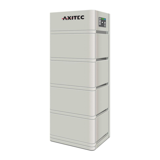
System Introduction 2.1 Product Introduction The AXIstorage Li SV2 is a high voltage battery storage system based on lithium iron phosphate batteries, which is a new energy storage product of Axitec. It can be used to provide reliable power for various types of equipment and systems. AXIstorage Li SV2 is especially suitable for those application which require high power output, limited installation space, restricted load-bearing and long cycle life. -
Page 10: Specifications
2.2 Specifications 2.2.1 System parameter Product Type AXIstorage Li SV2 Cell Technology Li-iron (LFP) Battery System Capacity(kWh) 7.10 10.65 14.20 Battery System Voltage(Vdc) Battery System Capacity(AH) 37Ah Battery Controller Name BMS SV2 Battery Module Name Energypack SV2 Battery Module Quantity(pcs) Battery Module Capacity(kWh) 3.552... -
Page 11: Battery Module (Energypack Sv2)
.2.2 Battery Module (Energypack SV2) Product Type Energypack SV2 Cell Technology Li-ion (LFP) Battery Module Capacity (kWh) 3.552 Battery Module Voltage (Vdc) Battery Module Capacity (Ah) Battery Module Serial Cell Quantity (pcs) Battery Cell Voltage (Vdc) Battery Cell Capacity (AH) Dimension (W*D*H, mm) 450*296*296 Weight (kg) -
Page 12: Control Module Bms Sv2 (Internal Power Supply)
2.2.3 Control Module BMS SV2 (internal power supply) Control Module (BMS SV2) Display Panel LED Button Short Press activates the LED panel for 20sec. Long Press When status LED is fast flashing blue ●, release the button, (more than then the baud rate of RS485 is 115200. 5sec) When status LED is fast flashing orange ●, release the button, then the baud rate of RS485 is 9600. - Page 13 Battery Module Status Blue solid Normal Orange solid Individual module alarm protection. See trouble shooting steps in section 5.1 System Capacity System SOC Each LED indicates 25%SOC LED Indicators Instructions Condition Note Self-checking Blue, Flashing All flashing Battery Module Status off. See Self-checking Orange, trouble shooting...
- Page 14 Power Switch ON: main breaker ON, it is now possible to turn on the battery system by start button. OFF: system turns off completely, no power output. Caution: When the breaker is tripped off because of over current or short circuit, wait at least 30min before turning on again, otherwise it may cause damage to the breaker.
-
Page 15: System Diagram
Channel spacing:5MHZ Type of antenna: 2.4G IPEX-SMA Antenna Power Terminal (+/-) For connecting the power cables between battery system and Inverter. Communication Terminal (RS485 / CAN / RS232) RS485 Communication Terminal: (RJ45 port) follow MODBUS 485 protocol, for communication between battery system and inverter. CAN Communication Terminal: (RJ45 port) follow CAN protocol, for communication between battery system and inverter. -
Page 16: Installation
Installation 3.1 Required Tools The following tools are required to install the battery pack: Wire Cutter Crimping Modular Plier Cable Ties Screwdriver Set Electric Screwdriver Adjustable Wrench Sleeve Piece 600VDC Multimeter NOTE Use properly insulated tools to prevent accidental electric shocks or short circuits. If insulated tools are not available, cover the entire exposed metal surfaces, except their tips, with available insulated alternatives (insulating tape). -
Page 17: System Working Environment Checking
The aeration shall avoid high salinity, humidity or temperature. Caution: The AXIstorage Li SV2 system has IP55 protection. But please avoid frost or direct sunlight. Conditions out of the working temperature range will cause the battery systems over / low temperature alarm or protection trigger which further leads to cycle life reduction. -
Page 18: Handling And Placement Of The Base
In cold area a heating system is required. B. The AXIstorage Li SV2 system must not be immersed in water. The battery base cannot be placed in rain or other water sources. As a suggestion, the base’s height shall be >300mm above the ground. -
Page 19: Mounting And Installation Of The Base
Energypack SV2 Battery Module Energypack SV2 battery module EPE foam No additional kits needed for AXIstorage Li SV2 installation. 3.4.5 Mounting and installation of the base The base must be fixed installed on the basement with 4pcs M8×80 foundation bolts. -
Page 20: Battery Modules And Control Module (Bms) Pile Up
3.4.6 Battery Modules and Control Module (BMS) pile up Handle the modules above the red marked edgings on both sides. Caution: If hands are under this red marked side, hands will get hurt. Danger: when the battery is connected together with the base, the internal sockets still have high voltage DC power from serial connected battery modules (battery module can’t be turned off). -
Page 21: Installation Of The Metal Mounting Rails
3.4.7 Installation of the metal mounting rails In the control module’s package there are 2pcs short and 2pcs long metal mounting rails. Fix these metal mounting rails at both back side corners. V220419... - Page 22 V220419...
-
Page 23: Locking Of The Control Module's Fix Screw On Left And Right Side
3.4.8 Locking of the control Module’s fix screw on left and right side 3.5 Cables connection Attention: Danger: The battery system is a high voltage DC system. Make sure the grounding is fixed and reliable. Danger: All the plugs and sockets of the power cables must be not reverse connected. Otherwise it will cause personal injury. -
Page 24: Grounding
3.5.1 Grounding The AXIstorage Li SV2 has three grounding points, where the grounding cable can be connected (above the right side of top metal mounting rail screw or beside both sides of the screw in the base). Connect the grounding cable to one of these grounding points. -
Page 25: Cables
3.5.2 Cables Note: For the power cables, water-proof connectors are used. To disconnect, a special tool is required. Do not pull out directly. Note: For communication cable use RJ45 connector and water-proof cover(M19-RJ45) matched with controller connection port. V220419... -
Page 26: Connection To Inverter
Consider the voltage range of the inverter when selecting the number of energy packs. If the storage model must be selected when configuring the inverter, select the Force H2 storage from Pylontech. The inverters listed in the table below are compatible with the AXIstorage Li SV2. Brand Inverter Type... -
Page 27: Switching On The System
3.7 Switching on the System Warning: Double check all the power cables and communication cables. Make sure the voltage of the inverter/PCS is same level with the battery system before connection. Check if all the power switches are OFF. Steps for switching system on: 1) Check if all cables are connected correctly. -
Page 28: Switching The System Off
failure in the battery string. The Power relays in the BMS will open, you must debug first. Note: The LED lamp will be off after 20sec without any operation. Caution: During first time power on, the system will require to do full charge progress for SOC calibration purpose. -
Page 29: Online Monitoring
3.9 Online Monitoring Online monitoring is possible via the SOLARMAN platform. For easier monitoring of the system status and further information in case of problems, online registration of the storage system is recommended. A WLAN connection must be available for this. Monitoring is possible both with the computer (https://home.solarmanpv.com/login) and with the smartphone (SOLARMAN Smart App). -
Page 30: System Debug
System Debug This system debug is for the Battery Energy Storage System (BESS). The system can’t do the debug itself. It must be operated with configured inverter, UPS, PCS and EMS system together. Debug Step Content Preparation of debug. Turn on the BESS, refer to chapter 3. Before turning on the whole BESS, turning on the load is not allowed! Remark: Except the BESS, if other equipment has its own system turn on steps, follow the operation manual. -
Page 31: Maintenance
Maintenance 5.1 Trouble Shooting: Danger: The AXIstorage Li SV2 is a high voltage DC system, operated by qualified and authorized persons only. Danger: Before checking the failure, check all cable connections and if the BESS can turn on normally or not. -
Page 32: Replacement Of Main Components
5.2 Replacement of main components Danger: The AXIstorage Li SV2 is a high voltage DC system, operated by qualified and authorized persons only. Danger: Before replacing a main component, shut down the maintenanced battery string’s power. - Page 33 5.2.1.3 Dismantle D+ and D- Power Cable, Communication Cable and Grounding Cable. 5.2.1.4 Dismantle the control Module’s fix screws of left and right side. And dismantle the fix metal mounting rails. 5.2.1.5 Move the control module and each battery module one by one. Danger: when battery is connected together with the base, the internal sockets still have high voltage DC power from serial connected battery modules (battery module can’t be turned off).
-
Page 34: Replacement Of Control Module (Bms)
5.2.2 Replacement of Control Module (BMS) 5.2.2.1 Turn off the whole battery string’s power. Make sure the D+ and D- terminals are without power. For the turn off progress refer to chapter 3.5.4. 5.2.2.2 Dismantle D+ and D- Power Cables, Communication Cable and Grounding Cable. 5.2.2.3 Dismantle the control Module’s fix screw on the left and right side and dismantle the fix metal mounting rails. -
Page 35: Battery Maintenance
5.3 Battery Maintenance Danger: The maintenance of the battery must be done by qualified and authorized personnel only. Danger: For some maintenance, the system must be turned off at first (Cables Inspection and Output Relay Inspection). 5.3.1 Voltage Inspection: [Periodical Maintenance] Check the voltage of the battery system through the monitoring system. Check the system whether there are abnormal voltages or not. -
Page 36: Remarks
2. In particular, special rules for the carriage of goods on the road and the current dangerous goods law, specifically ADR (European Convention on the International Carriage of Dangerous Goods by Road), as amended, must be observed. Any further questions, please contact Axitec: energy@axitecsolar.com V220419... -
Page 37: Annex 1: Installation And System Turn On Progress List
Annex 1: Installation and System Turn ON Progress List Tick after Item Remark completion The environment is meeting all technical requirements. 3.3.1 Cleaning 3.3.2 Temperature Refer to chapter ☐ 3.3.3 Fire-extinguisher System 3.3.4 Grounding System 3.3.5 Clearance Refer to chapter ☐... -
Page 38: Annex 2: System Turn Off Progress List
Soft-off the inverter through inverter’s control panel. 3.5.4. Turn off the switch between inverter and this battery string (AXIstorage Li SV2), or turn off the power switch of Refer to chapter ☐ inverter, to make sure no current flows through this 3.5.4.
Need help?
Do you have a question about the AXIstorage Li SV2 and is the answer not in the manual?
Questions and answers