Webasto 900 EX Installation, Operation And Maintenance Manual
Ev test systems
Hide thumbs
Also See for 900 EX:
- Installation, operation and maintenance manual (58 pages) ,
- Installation, operation and maintenance manual (56 pages)
Table of Contents
Advertisement
Quick Links
Advertisement
Table of Contents

Related Manuals for Webasto 900 EX


Summary of Contents for Webasto 900 EX
- Page 1 Installation, Operation, and Maintenance Manual EV Test Systems 900 EX...
- Page 2 DISCL AIMER: THIS MANUAL INCLUDES THE L ATEST INFORMATION AVAIL ABLE AT THE TIME OF PRINTING. WEBASTO CHARGING SYSTEMS, INC. RESERVES THE RIGHT TO MAKE CHANGES TO THIS MANUAL AND/OR PRODUCT WITHOUT FURTHER NOTICE. CHANGES OR MODIFICATIONS TO THIS PRODUCT NOT COMPLETED BY AN AUTHORIZED SERVICE PROVIDER COULD VOID THE PRODUCT WARR ANT Y.
- Page 3 A NOTE ABOUT CUSTOMER SUPPORT To ensure superior service, please write down the unit’s serial number in the owner’s record above and have it available when contacting Webasto customer support. The serial number can be found on the nameplate rating label on the upper left corner of the unit.
-
Page 4: Table Of Contents
1.1 Symbol Usage .................. 2 1.2 General Safety Precautions ............... 3 2 SYSTEM DESCRIPTION ..............5 2.1 About the 900 EX ................6 2.2 900 EX Power Applications .............. 6 2.3 System Components ................ 8 2.4 AC Inverter Functions & Controls ............. 9 2.5 DC Converter Functions &... - Page 5 DC I/O CONNECTOR ASSEMBLY ............51 B.1 Standard Unit with CAMLOCKS ............. 52 B.2 No CAMLOCKS Unit ..............53 APPENDIX C 900 EX REMOTE VOLTAGE SENSE OPERATION .......55 C.1 Remote Voltage Sense (RVS) Operation .......... 56 APPENDIX D HIGH VOLTAGE INTERLOCK WIRING ..........59 APPENDIX E INDEX .....................61...
-
Page 7: Introduction
Chapter 1 Introduction... -
Page 8: Symbol Usage
1.1 SYMBOL USAGE The 900 EX is designed with safety as the highest priority. Installation must comply with all local codes and the following safety precautions must be read and observed. Indicates information about safety practices which, if not followed, may result in serious injury or death. -
Page 9: General Safety Precautions
1.2 GENERAL SAFETY PRECAUTIONS BEFORE YOU BEGIN • Read all instructions and cautionary markings on the 900 EX assembly. • Read the important safety instructions below. • Leave these instructions with the installed unit for future reference. • Only qualified personnel should install, use, or service this unit. - Page 10 • Over temperature • Excess pressure • Excess gassing (H2) The HV Interlock on the 900 EX is provided to allow a hardware monitor to shut down the 900 EX in the event of an unsafe battery condition. Before attempting to service the system, follow these steps: 1.
-
Page 11: System Description
Chapter 2 System Description... -
Page 12: About The 900 Ex
(i.e., “cycling”) electric and hybrid-electric vehicle components and subsystems. The 900 EX is an ideal test system for a wide range of DC loads, in addition to batteries, offering more than a traditional power supply system. Examples include Auxiliary Power Units (APU), flywheels, motors, inverters, batteries, fuel cells, capacitors, and more. - Page 13 Category Application 900 EX Energy Storage Fuel Cell • Charging and Testing Super & Ultra Capacitors • Flywheels • Power Generation Electric Components • Equipment Testing Power Supplies • Generators • Stationary Power • Inverters • Military & Aerospace •...
-
Page 14: System Components
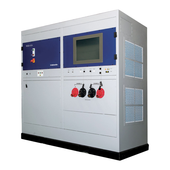
2.3 SYSTEM COMPONENTS Figure 1 and Table 2 illustrate and describe the 900 EX system components. Figure 1. System Components... -
Page 15: Ac Inverter Functions & Controls
Table 2. System Components Number Description (HMI) User Interface Panel Remote Operation System (ROS) Serial Port CAN BUS Port Remote Voltage Sense (RVS) - Channels A and B Multi-Unit Fiber (IN) Multi-Unit Fiber (OUT) Ethernet Fiber Multi-Unit Interlock High Voltage Interlocks - Channels A and B DC Output - Camlocks Option Isolation Fault Detection AC Diagnostic Port... - Page 16 Circuitry designed into the AC Inverter monitors the utility to detect any abnormalities. This is accomplished by measuring the frequency and amplitude of the utility and verifying that it remains within the specified range given in Section 2.6 Technical Specifications. The AC Inverter operates under current control instead of the more common phase control.
- Page 17 Once the contactors have been closed and the Unit Under Test (UUT) is connected to the 900 EX, the Isolation Monitor is disabled to prevent nuisance trips with low impedance loads.
- Page 18 Isolation Monitor trips. While this is happening, the Ready light (green) is flashing. The 900 EX will stay in this state until the voltage threshold is reached, or for a maximum of nine (9) seconds, after which the unit declares a Standby Fault.
-
Page 19: Dc Converter Functions & Controls
Once the fault is cleared, the light will return to a steady yellow, indicating the circuit is ready to resume monitoring and the 900 EX lockout has been released. 2.5 DC CONVERTER FUNCTIONS & CONTROLS The DC Converter monitors load connections, processes power from the Intermediate DC Bus for the load, and provides a local control interface. - Page 20 2.5.1 DC SIDE CONNECTOR INTERFACE All of the manual functions of the 900 EX are controllable with the ROS or other scripting tool. In addition, there are serial data output, CAN Bus, and ethernet connectors that are accessible on the DC Connector Panel (Figure 5). Details of the connector pin outs and the function of each are described below.
- Page 21 The ROS PC connects via RS-232 to the 900 EX (see Figure 7). 2.5.1.3 HV INTERLOCK (FRONT PANEL) Each channel of the 900 EX has a High Voltage Interlock Switch (HVIS) for added protection (see Figure 6). The HVIS can put one channel of the 900 EX into Standby Mode without affecting the other channel.
- Page 22 2.5.1.7 REMOTE EMERGENCY STOP (OPERATIONAL) Within the 900 EX there is a provision to allow installation of an external switch to control the emergency stop function of the system. To enable a system provided with this option, an electrical connection must be made between Pins 1 and 4 of this interface (Figure 9).
-
Page 23: Technical Specifications
Figure 9. Remote Emergency Stop 2.6 TECHNICAL SPECIFICATIONS Table 5 shows the features and Table 6 shows the operating range for the 900 Table 5. Product Features Parameter Description Input Rating (3 Phase) 480 V 440 V 415 V 400 V 380 V Current 344 A... - Page 24 Table 6. Operating Range Configuration Voltage (Vdc) Current (Adc) System Power (kW) ≥ Independent -500 to +500 -250 to +250 +8 to ≤+750 > -400 to +400 -225 to +225 +750 to ≤+825 > -300 to +300 -200 to +200 +825 to ≤+900 ≥...
-
Page 25: Installation
Chapter 3 Installation... -
Page 26: On-Site Installation
3.1.1.3 UTILIT Y REQUIREMENTS The input wiring block is located on the top left side of the 900 EX, see Figure 10. A 3 ½” diameter hole can be punched for a 3” conduit to accommodate 3 phase wires plus ground. - Page 27 3.1.2 VERIFY UNIT 3.1.2.1 INSTALLATION CHECKLIST Write down the unit serial number on the installation checklist (Figure 11). Figure 11. Installation Checklist...
- Page 28 ½” diameter bolts were provided for the 3 phase input connection, torque spec is 350 in.-lb • Ensure proper phase rotations 900 EX must be connected to an equipment grounding conductor run with the circuit conductors. Connections must comply with Chapter 2 and Electromagnetic Interference Section of ANSI/IEEE Standard 142-199, “Recommended Practice for Grounding of Industrial...
-
Page 29: Operation
Chap ter 4 Operation... - Page 30 • Over temperature • Excess pressure • Excess gassing (H2) The HV Interlock on the 900 EX is provided to allow a hardware monitor to shut down the 900 EX in the event of an unsafe battery condition. In Current, Power, or Resistance Mode, do not open or close the circuit under load.
-
Page 31: Channel To Channel Operation
Prepare two (2) cables with the appropriate connectors on either end that mate with those provided on the 900 EX unit. One cable should have red terminals on both sides and the other should have black connectors on both sides. -
Page 32: Choosing A Load Configuration
Figure 12. Planning Checklist 4.3 CHOOSING A LOAD CONFIGURATION Some loads and test plans may require a particular configuration of the 900 EX load connections. Figure 13 shows the Operating Limits for the following two configurations, Independent and Parallel. Each of the configurations is described in more detail... - Page 33 DC Converter has over its own output. A single load may be connected in Independent Configuration (i.e., either Load A or Load B) with no change in functionality. A load connected to an 900 EX in the Independent Configuration is illustrated in Figure 14.
- Page 34 Figure 14. Independent Configuration 4.3.2 EXTERNAL PARALLEL CONFIGURATION When in External Parallel Configuration, the Parallel Configuration is selected on the front panel as seen in Figure 15 and a single load is connected to both the positive and negative output terminals. Parallel Configuration is illustrated in Figure 15.
- Page 35 4.3.3 MULTI-UNIT CONFIGURATION Multi-Unit Configuration is selected on the front panel as seen in Figure 16. When in Multi-Unit Configuration, the load is connected to both the positive and negative output terminals of each paralleled unit. Multi-Unit Screen is shown in Figure 16 and Configuration is illustrated in Figure 17.
-
Page 36: Choosing Operating Limits
4.4 CHOOSING OPERATING LIMITS The 900 EX allows the set up of temporary upper and lower Operating Limits for voltage, current, and power that are more restrictive than the absolute system limits defined in the Operating Range table. In many cases, these more restrictive limits may be useful in order to protect the load or avoid unsafe conditions. -
Page 37: Operating The System
4.5 OPERATING THE SYSTEM The 900 EX is designed for easy operation. The flowchart (see Figure 18) describes the typical procedures to follow for any test. The steps are divided into Local Operation and Remote Operation. Depending on the test requirements, only some of these steps will be chosen. - Page 38 Figure 18. 900 EX Operation Flow Chart The 900 EX is designed to make setup and operation as easy as possible while ensuring safety. Once the system main power is on, the front panel HMI will start up and connect to the DC controller.
-
Page 39: System Start-Up
4.6 SYSTEM START-UP The DC Converter contains the controls to start the 900 EX. To start the system: Confirm that the RED light on the Main Power Off button on the AC Inverter front panel is illuminated to show that input power is available. If the RED light is not illuminated, confirm that the local disconnect is switched Press the Main Power On button. -
Page 40: Adjusting Operating Limits
When the 900 EX powers on, it will start in Independent Mode by default. g. To switch to Parallel Mode, select the Parallel mode from the HMI screen. h. To switch to Multi-Unit Mode, select the Multi-Unit Parallel mode from the HMI screen. -
Page 41: Selecting Local Or Remote Operation
Once the load has been connected and the load configuration has been chosen, the 900 EX is ready to run. At this point, the unit is in Local/Independent Mode operation by default. If ROS is running Remote Operation of each channel, it can be initiated;... - Page 42 4.9.1.1 SELECTING MODE • To select Voltage Control Mode, press the V button on the HMI screen (see Figure 20). This button lights up, while the other mode buttons (CURRENT: I, POWER: P and RESISTANCE: R) remain dimmed. Similarly, to select Current, Power, or Resistance Mode, press the HMI button corresponding to the mode.
- Page 43 Figure 21. Adjusting Settings Settings cannot be adjusted to a value outside the Operating Limits defined for the parameter being controlled. • If the DC Converter is unable to adjust the setting further without violating Operating Limits on parameters other than the one being controlled, it will not allow further adjustments.
- Page 44 at any time by pressing the desired command mode button on the HMI screen. The DC Converter will immediately switch to the new Control Mode. Example: the test is in Current Control Mode (CURRENT mode is highlighted) with output readings of 300 VDC, +50 ADC and 15 kW. If the Voltage Mode button is pressed, the DC Converter will change to Voltage Control Mode (Voltage Mode is highlighted) and begin controlling at 300 Volts.
- Page 45 Figure 23. Pausing or Stopping a Test To enter Standby Mode at any time, press the HMI STOP button for the appropriate converter (A or B). The unit will identify that it is in Standby mode. An audible click will be heard as the DC output contactors open and internally disconnect the load.
- Page 46 Once in remote operation, all control can be done from the ROS or other scripting tool. The ROS application provides the complete set of 900 EX front panel controls. Limits and mode selections are easily performed with a few clicks of the mouse.
-
Page 47: Turning Off Power
ROS. 4.10 TURNING OFF POWER To shut down the 900 EX at any time, press the OFF switch or depress the Emergency Off button (both on the AC Inverter front panel). However, in the event of a normal, non-emergency shutdown, it is recommended that the DC Converter be placed in Standby Mode (HMI “STOP”... -
Page 49: Maintenance
Chapter 5 Maintenance... -
Page 50: Preventative Maintenance
5.1 PREVENTATIVE MAINTENANCE The 900 EX requires minimal regular maintenance. Occasional preventative maintenance as described below should keep the system in good operating condition for many years. -
Page 51: Fault Indications
To aid with fault diagnosis, fault indicators have been built into the design of the 900 EX (see Figure 24). If a system shuts down due to a fault condition, look at the front panel to see if any of the fault lights are lit or fault codes displayed, and refer to Table 7 or if further explanation is needed for any fault messages displayed on the HMI, please contact customer service. - Page 52 Figure 24. Fault Display Table 7. Fault Indications Isolation Fault Indicator ±Bus Fault On Steady Loss of isolation between the positive or negative bus Isolation Fault Detection Reset Flashing Isolation fault has been latched...
-
Page 53: Glossary Of Terms
appendix a Glossary of Terms... - Page 54 30 percent (which will increase as the filter gets clogged). Battery Cycler A term for the 900 EX that refers to its use in battery charge and discharge cycling. Configuration The wiring arrangement used for a particular load or loads.
- Page 55 Term Definition DC Converter A subassembly of the 900 EX on the right side of the cabinet. Consists of two independently controllable converters (A and B), each regulating the output (load) terminals based on front panel settings or commands from a remote operation system.
- Page 56 This bus is not accessible to the user. Limits See “Operating Limits.” Load A device or system connected to the 900 EX for the purpose of receiving and/or delivering DC power. Local Operation Control of the DC Converter is achieved from the front panel.
- Page 57 Remote Operation A computer-based system that interacts with System (ROS) the 900 EX via the Remote Operation Interface. The remote operation system receives data and status information from the 900 EX and sends operating limit and control commands to the 900 EX.
-
Page 59: Dc I/O Connector Assembly
appendix B DC I/O Connector Assembly... -
Page 60: Standard Unit With Camlocks
B.1 STANDARD UNIT WITH CAMLOCKS Table 9. CAMLOCK Connector Part Numbers 900 EX Description Connector, Black 07033 Connector, Plug – ECT 170SS-350M, Black Connector, Red 07032 Connector, Plug – ECT 17DSS-350M, Red B.1.1 GENERAL The male and female contacts are attached to the cable (copper only) by means of a double set screw. -
Page 61: No Camlocks Unit
The simple and easy procedure for assembly or disassembly offers the flexibility to change or replace contacts and/or insulator sleeves in the field as well as easily reuse component parts B.2 NO CAMLOCKS UNIT B.2.1 EQUIPMENT REQUIREMENTS Flexible cable 350MCM, 1000Vac rated to connect to the 500A load. B.2.2 GENERAL The DC output cable entry hole is provided on the top of the unit in the front... - Page 62 Strip cable insulation back 1 inch from the end. Tighten the cable into the solid copper lug with a half inch (1/2”) stud size. Connect the lug with marked cable to the DC terminals.
-
Page 63: 900 Ex Remote Voltage Sense Operation
C 900 EX Remote Voltage Sense Operation... -
Page 64: Remote Voltage Sense (Rvs) Operation
C.1 REMOTE VOLTAGE SENSE (RVS) OPERATION Independent Mode The output voltage of each channel of the 900 EX can be regulated directly at the load, eliminating excessive voltage drop across the cables, which carry high current between the 900 EX and the load and yet maintain greater voltage accuracy. - Page 65 Figure 26. Connection Diagram for RVS in Independent Mode Parallel Mode In Parallel Mode, only the RVS connector on channel A is used with the load connected up as in Figure 13.
-
Page 67: High Voltage Interlock Wiring
appendix D High Voltage Interlock Wiring... - Page 68 DC Contactor. The firmware will recognize this event and open the other DC Contactor and put the system into Standby Mode, thus isolating the output of the 900 EX from the load. If a true hardware interlock is desired for both channels in Parallel Configuration,...
- Page 69 Appendix E Index...
-
Page 70: Index
Index Emergency Off 3, 4, 10, 11, 33, 39, 40, 42 External Parallel 13, 28 AC Inverter 9, 10, 11, 33, 40, 42, 46, 48 Fault Indications 43, 44 Fault Lights 12, 43 Bus Fault 11, 12 HV Interlock 4, 15, 24, 60 9, 13, 14, 16, 17 Control Mode 30, 31, 35, 36, 37, 46, 48... - Page 71 Main Power Selecting Mode 10, 11, 33, 39, 40 Maintenance Side A iii, 41, 42 Side B Standby 12, 15, 24, 35, 38, 39, 40, 46, 49, 60 Operating Space 30, 38, 48 Operation Flow Chart Utility 9, 20, 22, 49 Parallel Configuration 13, 28, 60 Power Applications...
- Page 72 22855-03-04...
Need help?
Do you have a question about the 900 EX and is the answer not in the manual?
Questions and answers