
Subscribe to Our Youtube Channel
Related Manuals for TBB idSWITCH LMP1218-PWM


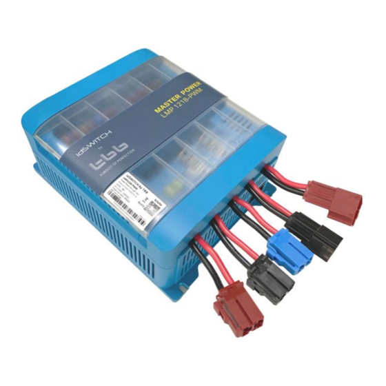
Summary of Contents for TBB idSWITCH LMP1218-PWM
- Page 1 LMP1218-PWM Master Power Unit User Manual LMP1218-PWM Master Power Unit Version : A1.0 Date: Apr. 2020 IDM Technologie...
- Page 2 LMP1218-PWM Master Power Unit User Manual WARNING : FIRE HAZARD SUITABLE FOR MOUNTING ON CONCRETE OR OTHER NON- COMBUS TABLE SURFACE ONLY CAUTION : THE DC AND AC BREAKER MUST HAVE BEEN TURNED OFF BEFORE SERVICING MADE IN CHINA IDM Technologie...
- Page 3 LMP1218-PWM Master Power Unit User Manual Unless specially agreed in writing, IDM Technologie. Ø Take no warranty as to the accuracy, sufficiency of suitability of any technical or other information provided in this manual or other documentation. Ø Assumes no responsibility or liability for loss or damage, whether direct, indirect, consequential or incidental, which might arise out of the use of such information IDM Technologie offer standard warranty with its products, taking no responsibility for direct Ø...
-
Page 4: Table Of Contents
LMP1218-PWM Master Power Unit User Manual General Safety Instruction..........................1 1.1 Safety Instruction ............................1 1.2 General Precaution ............................1 1.3 Precaution regarding battery operation ......................1 LMP1218-PWM INTRODUCTION........................2 2.1 Features................................ 2 2.2 LED Display ..............................3 KEY FEATURES AND FUNCTIONS ......................4 3.1 Multiple inputs ............................. -
Page 5: General Safety Instruction
LMP1218-PWM Master Power Unit User Manual 1. General Safety Instruction 1.1 Safety Instruction As dangerous voltages and high temperature exist within the LMP1218-PWM Master Power Unit, only qualified and authorized maintenance personnel are permitted to open and repair it. Please make sure the unit is turned off before open and repair it. -
Page 6: Lmp1218-Pwm Introduction
LMP1218-PWM Master Power Unit User Manual 2. LMP1218-PWM INTRODUCTION 2.1 Features Ø Smart battery charger 12V18A ² Active PFC charging ² Temperature compensated Charging ² Voltage compensated Charging Ø 16 Fused DC outputs, including water pump and lighting central control. Ø... -
Page 7: Led Display
LMP1218-PWM Master Power Unit User Manual 2.2 LED Display Table 1 LED indication Color Status Description Battery charged Flashing Battery charging Green (flash once every second) Battery discharge Battery discharging Dischg Orange Battery charging Green/Orange Both ON CHG/ Dischg Power supply IDM Technologie... -
Page 8: Key Features And Functions
LMP1218-PWM Master Power Unit User Manual 3. KEY FEATURES AND FUNCTIONS 3.1 Multiple inputs LMP master power unit may have multiple sources at one time. These sources include the Shore power, Solar panel and Alternator (Motor battery). There is priority among these sources, but LMP allows several sources to charge auxiliary battery at the same time. -
Page 9: Power Supply Mode
LMP1218-PWM Master Power Unit User Manual The LMP1218-PWM can be configured to charge Lithium battery. 3.3 Power Supply Mode If no battery is attached to LMP1218-PWM unit, it will work as a power supply automatically with a 12.8VDC output. 3.4 PWM Solar charger controller LMP has a built-in PWM charger for the service battery. -
Page 10: Dc Distribution
LMP1218-PWM Master Power Unit User Manual on-board. It protects the auxiliary battery from being drained by electronics on board, completely isolating the battery. 3.8 DC Distribution Figure 2 DC distribution schematic diagram IDM Technologie... -
Page 11: Structure And Installation
LMP1218-PWM Master Power Unit User Manual 4. STRUCTURE AND INSTALLATION 4.1 LMP1218-PWM Master Power Unit Figure 3 Connectors at front and back Table 3 Connector description DEFINITION LABEL DESCRIPTION AC input port AC input port Connect to PV Panel Fridge Connect to fridge Lifting Bed Connect to lifting bed... - Page 12 LMP1218-PWM Master Power Unit User Manual [1]15 GND : Buzzer Footstep [2]1 POS : Lighting Right side [2]2 GND : Lighting Right side [2]3 POS : Buzzer Footstep [2]4 POS : Lighting Left side [2]5 POS : Lighting Left side [2]6 GND: In/Out Footstep (COM) [2]7...
-
Page 13: Installation
LMP1218-PWM Master Power Unit User Manual [6]5 CW-100% [6]6 [5]1 CW-REF [5]2 CW-25% [5]3 CW-50% Fresh water tank [5]4 CW-75% [5]5 CW-100% [5]6 RS485 port Connect to RS485 bus CI Bus port Connect to CI bus [4]1 Wake-up [4]2 Communication [4]3 port [4]4... -
Page 14: Fuse Specification
LMP1218-PWM Master Power Unit User Manual Figure 5 Dimensions of LMP1218-PWM 4.3 Fuse specification Here is a list for the fuses installed on LMP1218-PWM. Please also take reference of Figure 2. IDM Technologie... - Page 15 LMP1218-PWM Master Power Unit User Manual Table 4 Fuse specification list Fuse No. DC loads Specification Awning light Pump 7.5A Auxiliarie Oven Lighting 1 Lighting 2 USB Socket Bedroom USB Socket Kitchen 12V Socket Kitchen Permanent SAT Antenna Permanent Autoradio Permanent Heating System Permanent TV-Demodulator Lifting Bed...
-
Page 16: Operation
LMP1218-PWM Master Power Unit User Manual OPERATION 5.1 Configuration on LMP1218-PWM You could set the battery type, VCR and Mode through LMP1218-PWM master power unit. 5.1.1 Dip switch setting There are dip switches for you to set VCR mode, Working mode and Battery type. Figure 6 Dip switch Table 5 Dip switch definition DIP SWITCH... -
Page 17: External Battery Switch(Rsw)
LMP1218-PWM Master Power Unit User Manual - Charger: When this mode is selected, the LMP will operate as a charger to charge the auxiliary battery as long as the network or qualified PV is introduced - Power supply: when this mode is selected, the LMP will produce a stable voltage of 12.8 Vdc to power the connected DC loads Dip switch for battery setting 5.1.1.2... -
Page 18: Daily Maintenance
LMP1218-PWM Master Power Unit User Manual 5.2 Daily Maintenance • Confirm the Battery Switch is switching on when you want to charge the battery with the AC grid. • Check the nominal battery voltage is 12Vdc. • When replacing the existing battery with a new one, please have the new battery fully charged by Grid for the first time to calibrate a precise battery SOC. -
Page 19: Trouble Shooting
LMP1218-PWM Master Power Unit User Manual Trouble shooting LED display on LMP-PWM Unit Table 8 Error LED indicator of LMP-PWM Color Status Description Flash once per cycle Service battery voltage low Green Flash twice per cycle Service battery voltage high CHG / / Orange DISCHG... -
Page 20: Specification
Connect delay time 10sec Charging Relay Disconnect voltage 12.8V Disconnect delay time 60sec High voltage limit 14.8Vdc Charge Algorithms TBB premium II - 5steps Battery type AGM/GEL/LFP/WET Charger mode Bulk current 18A(Max) Absorption voltage (14.4/14.1/14.4/14.7)±0.2Vdc Float voltage (13.5/13.5/13.5/13.7)±0.2Vdc Power supply Nominal output voltage 12.8±0.2Vdc... - Page 21 LMP1218-PWM Master Power Unit User Manual Battery charger disconnect, loads Battery over voltage limits disconnect Physical Specifications Dimensions (L*W*H) 235 × 185 × 98.5 mm Weight (kg) 2kgs Enclosure Plastic case Cooling Free cooling Protection category IP20 Approvals UN R10 IDM Technologie Web: www.idmtech.fr IDM Technologie...
Need help?
Do you have a question about the idSWITCH LMP1218-PWM and is the answer not in the manual?
Questions and answers
Waar zitten de dipschakelaars precies?
The dip switches on the TBB idSWITCH LMP1218-PWM are located on the master power unit.
This answer is automatically generated
Welke zekering is van de lader van de dynamo naar de huishoudaccu.
The fuse used for the TBB idSWITCH LMP1218-PWM charger from the alternator to the house battery is not specified in the provided information.
This answer is automatically generated
I have an LMP1218 PWM fitted to a 2024 Pilote P626D Evidence motorhome. I am going to change the existing AGM battery to a LiFePO4 battery and want to isolate the battery cabling from the Solar Panel PV system while I am working. Page 2, paragraph 2.1 Features suggests that there is a switch to isolate the battery when it is in storage. Can you please tell me where I find this switch and I operate it, as I've been unable to find it. Thank you.