Table of Contents
Advertisement
Quick Links
Advertisement
Table of Contents

Related Manuals for ICT CRX-POSTX-DIN

Summary of Contents for ICT CRX-POSTX-DIN
- Page 1 DIN Rail PostX IP Reporting Module Installation Manual...
- Page 2 Protege® and the Protege® Logo are registered trademarks of Integrated Control Technology Limited. All other brand or product names are trademarks or registered trademarks of their respective holders. Copyright © Integrated Control Technology Limited 2003-2016. All rights reserved. Publication Date: June 2017 CRX-POSTX-DIN DIN Rail PostX IP Reporting Module Installation Manual | June 2017...
-
Page 3: Table Of Contents
Programmable Outputs ....................24 7.4 Email Events ........................ 27 7.5 Ethernet Configuration ....................28 7.6 WiFi Configuration ....................... 29 7.7 GPRS / SMS Configuration ..................31 7.8 PSTN Configuration ..................... 31 CRX-POSTX-DIN DIN Rail PostX IP Reporting Module Installation Manual | June 2017... - Page 4 13.5 Panel Indicator......................43 13.6 Ethernet Indicator ......................43 13.7 Relay 1/Relay 2 Indicators ................... 43 13.8 Zone Status Indicators ....................44 13.9 WiFi Indicator....................... 44 13.10 GPRS Indicator ......................45 CRX-POSTX-DIN DIN Rail PostX IP Reporting Module Installation Manual | June 2017...
- Page 5 FCC Compliance Statements ______________________________________________ 62 Industry Canada Statement ________________________________________________ 64 Ordering Information ______________________________________________________ 65 Warranty ________________________________________________________________ 66 Contact _________________________________________________________________ 67 CRX-POSTX-DIN DIN Rail PostX IP Reporting Module Installation Manual | June 2017...
-
Page 6: Welcome
Online and remote upgradeable firmware For more information on the PostX DIN Rail IP Reporting Module and other Integrated Control Technology products please visit our website (http://www.ict.co). * Applies to WiFi and/or GPRS editions (see page 7) only. ... -
Page 7: Postx Module Editions
Ethernet, PSTN, WiFi or GPRS, according to the module used. Communication Interface Ethernet PSTN WiFi GPRS CRX-POSTX-DIN PostX DIN Rail IP Reporting Module CRX-POST-DIN-WF PostX DIN Rail IP Reporting Module with WiFi CRX-POSTX-DIN-GP PostX DIN Rail IP Reporting Module with GPRS CRX-POSTX-DIN-WFGP... -
Page 8: Installation Requirements
CAN/ULC-S561, Installation and Services for Fire Signal Receiving Centres and Systems The National Electrical Code, ANSI/NFPA 70 The Canadian Electrical Code, Part I, CSA C22.1 The Local Authority Having Jurisdiction (AHJ) CRX-POSTX-DIN DIN Rail PostX IP Reporting Module Installation Manual | June 2017... -
Page 9: Mounting
Insert a flat blade screwdriver into the hole in the tab at the top of the PostX Module. Lever the tab up and rotate the unit off the DIN Rail mount. CRX-POSTX-DIN DIN Rail PostX IP Reporting Module Installation Manual | June 2017... -
Page 10: Wiring Diagram
Data Transmission when using Resistor Zone Tamper, ground in the same cable. Do not use extra wires to Short power devices.) max 900m (3000ft). CRX-POSTX-DIN DIN Rail PostX IP Reporting Module Installation Manual | June 2017... -
Page 11: Dc Power
The 330 Ohm EOL (End of Line) resistor provided in the accessory bag MUST be inserted between the NA and NB terminals of the ACC-485 module directly connected to the PostX module.. ACC-485 CRX-POSTX-DIN 330R End of Line Resistor CRX-POSTX-DIN... -
Page 12: Interface Connections
It is recommended that the earth connection for the telephone and main power supply (see page 11) earth be run separately and should be terminated on the cold water pipe or similar grounding point within the installation. CRX-POSTX-DIN DIN Rail PostX IP Reporting Module Installation Manual | June 2017... -
Page 13: Ethernet 10/100 Network Interface
Ethernet 10/100 Switch/Hub Connection Temporary direct connections can be used for onsite configuration by using a standard Ethernet cable. PostX One Computer for configuration Ethernet 10/100 Direct Connection CRX-POSTX-DIN DIN Rail PostX IP Reporting Module Installation Manual | June 2017... -
Page 14: Gprs Interface
This information only applies to the PostX modules that support GPRS and/or WIFI communication. The antenna must be installed outside the DIN Rail cabinet. Antenna WIFI ZONE INPUT 1-4 12VDC OUT Cabinet WiFi Antenna connection CRX-POSTX-DIN DIN Rail PostX IP Reporting Module Installation Manual | June 2017... -
Page 15: Interface Configuration
Microsoft® Windows 7 http://windows.microsoft.com/en-US/windows7/Change-TCP-IP-settings Should the IP address need to be restored to the default value, please refer to the section on IP Troubleshooting (see page 37) for more details. CRX-POSTX-DIN DIN Rail PostX IP Reporting Module Installation Manual | June 2017... -
Page 16: Web Interface
Please refer to Web User Management (see page 36) for more details about user login. CRX-POSTX-DIN DIN Rail PostX IP Reporting Module Installation Manual | June 2017... -
Page 17: Routing Setup
7.2 Routing Setup To configure the routing options select the Routing Setup link using the web interface. The following shows an example configuration for the PostX Module. CRX-POSTX-DIN DIN Rail PostX IP Reporting Module Installation Manual | June 2017... -
Page 18: General Options
Using UDP to send the messages is faster than TCP as it is a connectionless protocol, the ArmorIP (UDP) protocol includes acknowledge and retry messages to ensure that the message has been received by the server. CRX-POSTX-DIN DIN Rail PostX IP Reporting Module Installation Manual | June 2017... - Page 19 This format uses TCP as the transport layer and communicates with central station receivers supporting that format. Patriot LS30 This TCP format communicates with the LS30 task in Patriot alarm monitoring software. CRX-POSTX-DIN DIN Rail PostX IP Reporting Module Installation Manual | June 2017...
-
Page 20: Pstn Reporting Formats
As with the reporting and polling sequences, the communication failure sequence is on a module base, meaning that a communication failure message will be reported once on only one channel, the first that succeeds. CRX-POSTX-DIN DIN Rail PostX IP Reporting Module Installation Manual | June 2017... -
Page 21: Input And Output Control
When using the EOL resistor configuration, the zone input is in the closed state when there is 1k Ohm resistance between the terminal and ground. If the zone contact opens, leaving 2k Ohm resistance between the terminal and ground, the zone moves into the open state. CRX-POSTX-DIN DIN Rail PostX IP Reporting Module Installation Manual | June 2017... - Page 22 The Zone Number or User Number is the 3 digit code to indicate the specific zone that has had the event. Use 000 to indicate that there is no specific zone or user information. CRX-POSTX-DIN DIN Rail PostX IP Reporting Module Installation Manual | June 2017...
- Page 23 To have an input send an email, the Send Email Message option must be enabled. For the settings shown above, when the input opens, the following email will be sent by the PostX Module: Site Name: ICT PostX Module Zone Message: Zone 1 Opened...
-
Page 24: Programmable Outputs
For the settings shown above, when the input opens, the following SMS will be sent by the PostX Module: Site Name: ICT PostX Module Zone Message: Zone 1 (Zone 1) Opened Time Stamp: 13:00:26 27/02/2013 Programmable Outputs The PostX Module has 2 programmable outputs. These outputs can be configured to be activated when the PostX Module loses a connection. - Page 25 Any Channel Failure Channel 1 Failure Channel 2 Failure Channel 3 Failure Channel 4 Failure Primary Ethernet Gateway Failure Secondary Ethernet Gateway Failure CRX-POSTX-DIN DIN Rail PostX IP Reporting Module Installation Manual | June 2017...
- Page 26 If the activation password is wrong, no response is sent to the user even if an acknowledgment is requested. CRX-POSTX-DIN DIN Rail PostX IP Reporting Module Installation Manual | June 2017...
-
Page 27: Email Events
Once the settings are entered, click Test Account Settings… to send a test email. The PostX Module will attempt to send an email to the address specified. If it does not get through in a reasonable amount of time, recheck your settings. CRX-POSTX-DIN DIN Rail PostX IP Reporting Module Installation Manual | June 2017... -
Page 28: Ethernet Configuration
Once all the changes have been made, click Save to save the changes. You must restart the PostX Module for the changes to take effect. CRX-POSTX-DIN DIN Rail PostX IP Reporting Module Installation Manual | June 2017... -
Page 29: Wifi Configuration
Always consult the network or system administrator and ask them to provide you with a fixed IP Address that can be assigned to the PostX Module. CRX-POSTX-DIN DIN Rail PostX IP Reporting Module Installation Manual | June 2017... - Page 30 Click Stop to exit scanning mode and return to enter parameters manually. Click Save to save the network you have selected and return to enter parameters manually. CRX-POSTX-DIN DIN Rail PostX IP Reporting Module Installation Manual | June 2017...
-
Page 31: Gprs / Sms Configuration
PABX Number This is the number the panel dials to obtain an external line and must be set if the PABX emulation is enabled. CRX-POSTX-DIN DIN Rail PostX IP Reporting Module Installation Manual | June 2017... -
Page 32: Advanced Configuration
Advanced Configuration CRX-POSTX-DIN DIN Rail PostX IP Reporting Module Installation Manual | June 2017... -
Page 33: General Settings
When checked, the PostX will send a message to the monitoring station. System Started Event Code This is the standard 3 digit Contact ID event code to indicate the type of event that is being reported. CRX-POSTX-DIN DIN Rail PostX IP Reporting Module Installation Manual | June 2017... -
Page 34: Csv-Ip Settings
Clicking this button will update the time remaining display. Note that the PSTN Pass Through feature can also be accessed locally via command line. Refer to the section on Command Line Interface Commands for details. CRX-POSTX-DIN DIN Rail PostX IP Reporting Module Installation Manual | June 2017... -
Page 35: Duplicate Configuration
Type in the following command using the IP address of the PostX Module: tftp –i 192.168.1.2 PUT config.bin Restart the PostX Module for the new configuration to take effect. CRX-POSTX-DIN DIN Rail PostX IP Reporting Module Installation Manual | June 2017... -
Page 36: Web User Management
10.3 Default Users The PostX Module comes with the following two default users: Username Password Access Level admin admin Administrator user user User CRX-POSTX-DIN DIN Rail PostX IP Reporting Module Installation Manual | June 2017... -
Page 37: Ip Troubleshooting
Connect the terminals for Zone 2 and NO of Relay 1 together. Repeat the procedure for the V- and C terminals as shown in the diagram below. Enable DC supply to the PostX Module. CRX-POSTX-DIN DIN Rail PostX IP Reporting Module Installation Manual | June 2017... -
Page 38: Confirm Ip Address Via Command Line
The second image shows a successful ping attempt where the IP address was found. Console screenshot of a Ping where the IP address cannot be found Console screenshot of a Successful Ping CRX-POSTX-DIN DIN Rail PostX IP Reporting Module Installation Manual | June 2017... -
Page 39: Command Line Interface
PostX Module and an available RS232 serial port on your computer. Open a terminal program such as HyperTerminal or TeraTerm with the baud rate set to 38400 (38400, 8, n, 1). Press ENTER or ESC to get the command prompt. CRX-POSTX-DIN DIN Rail PostX IP Reporting Module Installation Manual | June 2017... -
Page 40: Command Line Interface Commands
Sets the subnet mask. The PostX must be restarted for the change to take effect. set dnsl set dnsl 192.168.1.1 Sets the primary DNS server. The PostX must be restarted for the change to take effect CRX-POSTX-DIN DIN Rail PostX IP Reporting Module Installation Manual | June 2017... - Page 41 Resets the WIFI parameters to factory defaults wifi reset wifi reset Restarts the WIFI module wifi set ssid wifi set ssid ICT Sets the SSID parameter (case sensitive) of the WIFI module wifi set password wifi set password 1234ab Sets the access point password key of the WIFI module...
-
Page 42: Led Indicators
The Fault indicator is lit any time the module is operating in a non-standard mode. State Description Module is in boot mode awaiting firmware Slow (red) flash update CRX-POSTX-DIN DIN Rail PostX IP Reporting Module Installation Manual | June 2017... -
Page 43: Modem Indicator
The Relay 1 and Relay 2 indicators will show the status of the lock output relay. State Description On (red) Relay output is ON Relay output is OFF CRX-POSTX-DIN DIN Rail PostX IP Reporting Module Installation Manual | June 2017... -
Page 44: Zone Status Indicators
Connected RSSI level 2 WiFi constantly on / 3 bars on Connected RSSI level 3 Connected RSSI level 4 WiFi constantly on / 4 bars on (highest signal strength) CRX-POSTX-DIN DIN Rail PostX IP Reporting Module Installation Manual | June 2017... -
Page 45: Gprs Indicator
Connected RSSI level 2 GPRS constantly on / 3 bars on Connected RSSI level 3 Connected RSSI level 4 GPRS constantly on / 4 bars on (highest signal strength) CRX-POSTX-DIN DIN Rail PostX IP Reporting Module Installation Manual | June 2017... -
Page 46: Identification Sticker Details
MAC address of the PostX Module. An example of the identification sticker is shown in the diagram below. MAC Address Din Rail PostX IP Module Product Code CRX-POSTX-DIN 00:1B:C2:72:D3:E6 1005135000 HW Version Software Boot Version 02.02.00002... -
Page 47: Warnings
Should the matter be reported to Telecom as a wiring fault, and the fault is proven to be due to this product, a call-out charge will be incurred. CRX-POSTX-DIN DIN Rail PostX IP Reporting Module Installation Manual | June 2017... -
Page 48: Mechanical Diagram
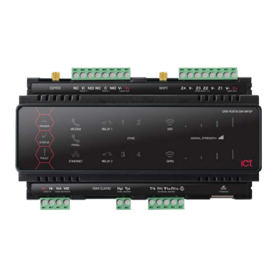
Relay 1 / Relay 2 GPRS Connector 12VDC Pass Through LED Indicators Signal Indicators Ethernet Interface 12VDC Input RS-485 Input External Modem Interface SIM Card Panel Modem Interface CRX-POSTX-DIN DIN Rail PostX IP Reporting Module Installation Manual | June 2017... -
Page 49: Mechanical Layout
17 Mechanical Layout The mechanical layout shown below outlines the essential details needed to help ensure the correct installation of the PostX Module. 156.8mm CRX-POSTX-DIN FRONT CRX-POSTX-DIN BACK 143.5mm 156.8mm CRX-POSTX-DIN DIN Rail PostX IP Reporting Module Installation Manual | June 2017... -
Page 50: Technical Specifications
Integrated Control Technology continually strives to increase the performance of its products. As a result, these specifications may change without notice. We recommend consulting the ICT website (http://www.ict.co) for the latest documentation and product information. Power Supply... -
Page 51: New Zealand And Australia
19 New Zealand and Australia General Product Statement The RCM compliance label indicates that the supplier of the device asserts that it complies with all applicable standards. CRX-POSTX-DIN DIN Rail PostX IP Reporting Module Installation Manual | June 2017... -
Page 52: Ul And Ulc Installation Requirements
10 min prior to the auto arming taking place. The control unit shall allow authorized users to cancel the auto arming sequence and transmit such cancelation to the signal receiving center with the identification of the authorized user that canceled the action. CRX-POSTX-DIN DIN Rail PostX IP Reporting Module Installation Manual | June 2017... - Page 53 Multiplex System and Poll Time The PRT-CTRL-DIN is compatible with the ICT ArmorIP Internet Monitoring Receiver. Poll Time must be set to 40 seconds and the Grace Time must be set to 20 seconds. In the Protege System, the reporting service must be configured to 40 seconds. The following options are required for the service selected as Report IP type: ...
- Page 54 CAN/CSA-C22.2 No. 60950-1 is adequate. Such components include, but are not limited to: A) Hubs; B) Routers; C) Network interface devices; CRX-POSTX-DIN DIN Rail PostX IP Reporting Module Installation Manual | June 2017...
-
Page 55: Can/Ulc-S319-05
Signal Reporting Any fault of an active communication system shall be annunciated and recorded at the signal receiving center within 180 s of the occurrence of the fault. CRX-POSTX-DIN DIN Rail PostX IP Reporting Module Installation Manual | June 2017... - Page 56 NOTE: Any available dry relay contact on the PRT-CTRL-DIN or PRT-PX8-DIN may be used for the FACP system, provided the selected output is programmed as the Report OK PGM. CRX-POSTX-DIN DIN Rail PostX IP Reporting Module Installation Manual | June 2017...
- Page 57 Open, Close, Tamper, Short Open, Close, Tamper, Short Open, Close, Tamper, Short Open, Close, Tamper, Short * EOL resistor must be installed at the Fire Alarm Control Panel Output. CRX-POSTX-DIN DIN Rail PostX IP Reporting Module Installation Manual | June 2017...
- Page 58 Protege GX Operator Reference Manual (227-1500-000) Fire zones Z1-Z3 shall be used exclusively for fire monitoring and cannot be programmed to activate the bell output. CRX-POSTX-DIN DIN Rail PostX IP Reporting Module Installation Manual | June 2017...
-
Page 59: Ul Compliance Requirements
In the Protege System, the reporting service selected as Contact ID must have the number of attempts programmed to 5 attempts. The following options are required: CRX-POSTX-DIN DIN Rail PostX IP Reporting Module Installation Manual | June 2017... -
Page 60: Ul294
If fire resistance is required for door assembly, portal locking device(s) must be evaluated to UL10B or UL10C. Must be installed with UL 1034 listed electronic locks for UL installations. CRX-POSTX-DIN DIN Rail PostX IP Reporting Module Installation Manual | June 2017... - Page 61 If a flexible cord is used to connect to line voltage, strain relief must be provided for the cord inside the enclosure or at the knockout. The Power Supply is not intended to be mounted on the exterior of vault, safe, or stockroom. CRX-POSTX-DIN DIN Rail PostX IP Reporting Module Installation Manual | June 2017...
-
Page 62: Fcc Compliance Statements
It is designed to be connected to a compatible modular jack that is also compliant. See this document for details. CRX-POSTX-DIN DIN Rail PostX IP Reporting Module Installation Manual | June 2017... - Page 63 Equipment Maintenance Facility If trouble is experienced with this equipment (CRX-POSTX-DIN), for repair or warranty information, please contact Integrated Control Technology c/o 150 W 9th Ave, Denver, CO 80204. If the equipment is causing harm to the telephone network, the telephone company may request that you disconnect the equipment until the problem is resolved.
-
Page 64: Industry Canada Statement
être raccordés à une interface téléphonique. La terminaison d’une interface peut consister en une combinaison quelconque de dispositifs, à la seule condition que la somme d’indices d’équivalence de la sonnerie de tous les dispositifs n’excède pas 5. CRX-POSTX-DIN REGISTRATION NUMBER IC: 10012A-CRXPOSTXDIN CRX-POSTX-DIN NUMÉRO D'ENREGISTREMENT... -
Page 65: Ordering Information
CRX-POSTX-DIN-WF with WIFI interface CRX-POSTX-DIN-GP with GPRS interface CRX-POSTX-DIN-WFGP with WIFI and GPRS interface Manuals and additional literature are available on the ICT Website (http://www.ict.co). CRX-POSTX-DIN DIN Rail PostX IP Reporting Module Installation Manual | June 2017... -
Page 66: Warranty
ICT's obligation and liability under this warranty is expressly limited to repairing or replacing, at ICT's option, any product not meeting the specifications. In no event shall ICT be liable to the buyer or any other person for any loss or damages whether direct or indirect or consequential or... -
Page 67: Contact
25 Contact Integrated Control Technology welcomes all feedback. Please visit our website (http://www.ict.co) or use the contact information below. Integrated Control Technology P.O. Box 302-340 4 John Glenn Ave North Harbour Post Centre Rosedale Auckland North Shore City 0632 New Zealand... - Page 68 Integrated Control Technology Limited 4 John Glenn Avenue, Rosedale, Auckland 0632 PO Box 302-340, North Harbour, Auckland 0751, New Zealand Email: sales@ict.co Toll Free: (0800) 428 111 Phone: 64 (9) 476 7124 AMERICAS Integrated Control Technology (USA) LLC 5265 S Rio Grande Street, Suite 201, Littleton, CO 80120 Email: ussales@ict.co Toll Free: (855) 428 9111 Phone: 720 442 0767...
Need help?
Do you have a question about the CRX-POSTX-DIN and is the answer not in the manual?
Questions and answers