Advertisement
Quick Links
Advertisement

Related Manuals for SIM DATAVIEW

Summary of Contents for SIM DATAVIEW
- Page 1 USER MANUAL DATAVIEW...
- Page 2 Index General Description Technical Features Keypad Basic Actions Acquisition HOLD OFFSET SCALE GAIN SETUP P1/P2 – P3/P4 Connections Software Installation Uninstall Start Communication Port Date & Time Configuration Getting Default Sending File Data Help Exit...
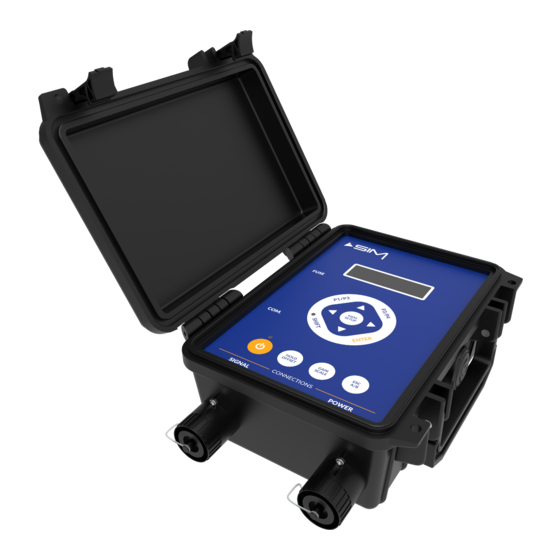
- Page 3 General Description The manual readout unit DATAVIEW is a compact and light reading system, connectable to the whole range of instruments produced by SIM STRUMENTI. The DATAVIEW readout unit is equipped internally with a rechargeable battery. The DATAVIEW is equipped with a membrane keyboard and an LCD display that visualize besides the instrument data also the maximum and minimum values.
-
Page 4: Technical Features
Technical Features Internal Power Supply Rechargeable battery 12V 2.1Ah External Power Supply 12V Power supply Consumption 125 mA Converter 40.000 points 1. 2 mV/V 2. ± 20 mV 3. ± 200 mV Available Scales * 4. ± 2 V 5. ± 10 V 6. - Page 5 Keypad Fig. 1 - DATAVIEW interface...
- Page 6 Basic Actions By pressing the ON/OFF button, DATAVIEW will turn on and the display will show the initialization screen and then date and time (which will be editable in the SETUP function). By pressing SHIFT , you can select the 2...
- Page 7 OFFSET By pressing SHIFT first and then HOLD/OFFSET during the acquisition phase, DATAVIEW will enter the OFFSET function, which allow you to deduct this value just measured (TARE) from the reading. The letter O will flash on the top right of the display.
- Page 8 By pressing SHIFT and then GAIN/SCALE , you can choose the measurement scale you want to use. There are up to 6 scales available*, which allow you to connect every SIM instruments. *In the DW-BSE model, there is only 1 scale available and it must be...
- Page 9 GAINS (analog signal scaling). The first cannot be modified and it corresponds to the chosen scale. The others can be modified in the SETUP function or with the DATAVIEW software. By using the UP and DOWN arrows, you can select the desired GAIN.
- Page 10 Connections POWER connector PIN 1 = + Supply 12-13,8 Vcc External Battery PIN 2 = - Supply PIN 3 = N.C. PIN 4 = N.C. SIGNAL connector PIN 1 = INPUT + Channel A PIN 2 = INPUT - Channel A PIN 3 = INPUT + Channel B PIN 4 = INPUT - Channel B PIN 5 = Ground...
-
Page 11: Installation
Software DATAVIEW software is used to setup and to download the data stored in the readout unit. DATAVIEW software can be supplied on a USB key or it can be downloaded directly from SIM STRUMENTI website, in the downloads section: https://www.simstrumenti.com/downloads/software/... - Page 12 Img. 2 An installation window will open and there will be the need to wait that the Preparing to install will be completed (Img.3). Img. 3 On the following window (Img.4), click on Next to proceed with the installation, or on Cancel to interrupt it.
- Page 13 By continuing with the installation (Img.5) in which it will be possible to change the destination folder for the DATAVIEW software. To keep going, click on Next . Img. 5 On the next window (Img.6) click on Install to proceed with the actual installation.
- Page 14 Img. 7 At the end, another window (Img.8) will show up to confirm DATAVIEW software has been successfully installed. Click now on FINISH . Img. 8...
- Page 15 Uninstall In the case there will be the need to uninstall DATAVIEW software, there is a special program called UNINSTALL DATAVIEW x.x. To uninstall, proceed in the following way: START PROGRAMS DATAVIEW UNINSTALL DATAVIEW x.x For the uninstall procedure of the software, a window will come up where there will be the need to confirm the uninstall process (Img.9).
- Page 16 Start To start the DATAVIEW software, proceed in the following way: START PROGRAMS DATAVIEW DATAVIEW x.x Img. 11 During the loading of the program, it will be visible the boot screen (Img.11) and after it will appear a window (Img.12) to choose the device with which you want to connect.
- Page 17 Img. 13 Img. 14...
- Page 18 Main screen sections DATAVIEW DATAFLOW Menu bar Menu bar Data grids (one tab for each scale) Setting tabs Buttons to set and receive data from the unit Buttons to set and receive data from the unit Menu bar DATAVIEW DATAFLOW •...
-
Page 19: Communication Port
DATAVIEW/DATAFLOW. In case of a connection to a DATAVIEW, a communication window will appear (Img.15), asking if you want to continue receiving the stored data. Click Yes to confirm. - Page 20 DATAVIEW The Gain 1 in each scale is displayed with a grey background because it has default values that cannot be changed. Editable Data in DATAVIEW Shows the number of digits after the point. Decimal Point It is possible to insert a value between 0 and 5.
- Page 21 Shows the number of digits after the point. Decimal Point It is possible to insert a value between 0 and 5. Shows the unit of measure. Unit It is possible to insert up to 4 alphanumeric digits. Flow Conversion Displays the value to offset the converted measurement. Offset It is possible to insert a value between –99999 and +99999.
- Page 22 In the lower left frame named SET INTO PANEL , are placed the buttons needed to set the values into the device. DATAVIEW By pressing this button, you can send only the scale that is displayed. It will appear a communication window with a progress bar (Img.16).
- Page 23 Img. 18 File The software allows to save the configuration data inserted, in order to provide a backup and an easy restore of the device. To save the data, press the button A communication window will appear (Img.19) asking for the location and the file name.
- Page 24 Img. 19 By pressing the button , a window will appear (Img.20) asking for the location and the file to load. Img. 20...
- Page 25 Data As explained before, DATAVIEW and DATAFLOW devices can store up to 9999 readings. The software allows to access this data extremely easy, creating a textual file. DATAVIEW Click Data Transfer in the menu bar of the main screen. DATAFLOW Click on the button placed in the DataFlow Settings tab.
- Page 26 Img. 22 Help Click Help on the menu bar to open the below popup: Click Contents , if you want to see the software and hardware user manual. Click About , if you want to see the informations about this software version (Img.23). Img.
- Page 27 Exit Click Exit to terminate the program. A confirmation window will appear (Img.24). Click Yes to end the program or No to cancel the request. Img. 24...
- Page 28 NOTES...
- Page 29 NOTES...
- Page 30 Sim Strumenti S.n.c. Via Merendi 42 20010 CORNAREDO (MI) ITALY Tel: +39 02 9700 30 39 Fax: +39 02 9729 01 67 www.simstrumenti.com sim@simstrumenti.com...
Need help?
Do you have a question about the DATAVIEW and is the answer not in the manual?
Questions and answers