
Related Manuals for SIM 2W-SIROUT-S

Summary of Contents for SIM 2W-SIROUT-S
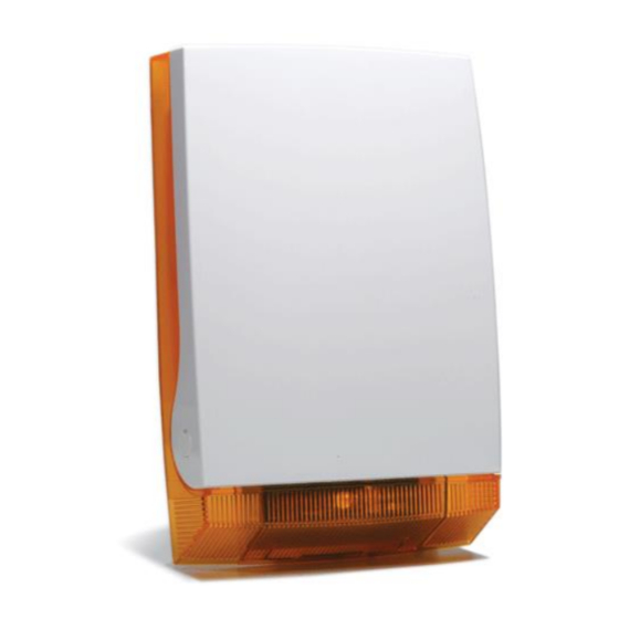
- Page 1 2W-SIROUT-S Two Way Outdoor Sounder With Battery INSTALLATION MANUAL P/N 7106663 Rev A...
-
Page 2: Table Of Contents
Contents INTRODUCTION ........................2 ..................2 ENERAL ESCRIPTION 2W-SIROUT-S I RUNNER 2 NTRODUCTION TO ............2 ..................3 IREN ESCRIPTION 2W-SIROUT-S RUNNER 2 ETTING THE CONFIGURATION ........3 STEP 1: FW2-TRANSCEIVER – L & O EARNING PERATING ODE FOR RUNNER 2 .................... -
Page 3: Introduction
The 2W-SIROUT-S unit can be powered by Lithium Battery 3.6V/14Ah or by external power supply 12V/0.8A or both. SIM TX/RX-PB-S Introduction into the SIM Panel SIM TX/RX-PB-S can be installed in selected SIM panel or in an external box while protected by the on boards tamper Figure 1... -
Page 4: Siren Unit Description
The signal transmitted to Transceiver: Synchronization, Acknowledge, Tamper and Low battery. The Siren can be assigned to Area A or Area B by jumper selection –See Table 1 Setting the 2W-SIROUT-S for SIM Panels configuration STEP 1: SIM TX/RX-PB-S – Learning & Operating Mode for... -
Page 5: Physical Description
Physical Description STEP 2: Setting the Siren Configuration Mode Figure 2: Siren Description Diagram The Siren unit can be powered by Lithium Battery 3.6V/14Ah or by external power supply 12V/0.8A or both, in case of both the battery use as backup. NOTE: refer to table 1 for Jumpers set-up on the next page... - Page 6 Siren's Jumper's MODE SET-UP Jumper No. Function if = O (Open) Function if =1 (Close) Not in used for RUNNER 2 and SERENITY control panels Flashes appear with ARM/Disarm Arm: 2 Flashes (@LOW BAT 3+3 NO Flashes with ARM/Disarm Flashes) Disarm: 1 Flash (@LOW BAT 2 Flashes) Beeps sound with ARM/Disarm...
-
Page 7: Step 3 : Learning The Sirens
STEP 3 : Learning the Sirens Up to 8 Siren units can be activated by single Transceiver. In BUS Mode, these Sirens can be divided to two groups (A&B) for activating their Sirens (by receiving two separate activation controls). Instruction Description Place the Siren Units on a flat To verify back tamper is closed. -
Page 8: Installation Instructions
Installation Instructions Installing the Transceiver 1. Choose a central location for the installation of the Transceiver to insure radio coverage to all the Siren Units. Open the Screw (See Figure‐6) and open the cover. 3. Place the unit on the installation surface and mark out the four screw holes. 4. -
Page 9: Installing The Siren Units
Installing the Siren Units A Transceiver can control up to 8 Sirens. It is recommended that the units be installed on a flat surface in a prominent location. To install the Siren in each location: 1. Choose a location for each one for the installation of each Siren units. Make sure that there is Radio coverage to this location from the Transceiver. - Page 10 5. Use a 8 mm bit to drill the holes Battery Address Jumpers 12 Volt Connector PIEZO Siren Connector Battery Connector Figure 4: Open Siren Unit 6. Fix the unit onto the installation surface. 7. Ensure that the Piezo Siren is connected to the Piezo connector (as shown below).
-
Page 11: Maintenance14
Maintenance Low Battery Indication The battery is tested every 4 hours and after power‐up. When the Siren battery is low more beeps are added to the ARM/Disarm beeps in order to indicate the LOW BAT condition of the Siren unit. When Arming the Siren there are 3 beeps, short pause and another 3 beeps instead of two beeps and when Disarming the Siren there will be 3 beeps instead of one. -
Page 12: Specification: Siren Unit
Specification: Siren Unit FW-Siren Specification (External Unit) Value Sound Pressure Level More then 102dB Siren Tone Yelp Frequency Range 2700 ±500 Hz Flash Light Power LED (90 Lumens) Power Supply Voltage 9V÷15V DC or Battery 3.6V /14Ah Lithium or both. Current consumption Standby: 110uA ±10uA@ Battery operation 20mA±2mA@12V DC operation.. -
Page 13: Specification: Transceiver Unit
Specification: Transceiver Unit Transceiver Specification (Remote) Value Power Supply 9V-14V DC Current Consumption Receive:30mA±5mA Transmit:40mA±5mA Max power Operating temperature range -10oC to +50oC Ambient temperature, storage -20oC to +70oC Inputs IN-1: Trigger Alarm. IN-2: Trigger Key Arm/Disarm BUS Connection via Fast Connection or Terminals Outputs Tamper Out Terminals , Dry contacts 12V DC/100mA... - Page 14 www.sim-security.net...
Need help?
Do you have a question about the 2W-SIROUT-S and is the answer not in the manual?
Questions and answers