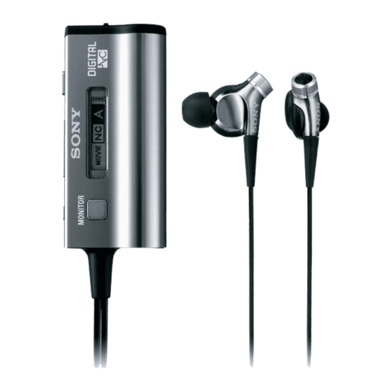
Sony MDR-NC300D Service Manual
Noise canceling headphones
Hide thumbs
Also See for MDR-NC300D:
- Product information (124 pages) ,
- Operating instructions (2 pages) ,
- Specifications (2 pages)
Advertisement
Quick Links
SERVICE MANUAL
Ver. 1.2 2010.01
SPECIFICATIONS
General
Type:
dynamic, closed
Wear method:
vertical in-the-ear
Driver units:
16 mm, dome type
(CCAW adopted)
Power handling capacity:
100 mW
Impedance:
16 Ω (at 1 kHz)
Sensitivity:
103 dB/mW
Frequency response:
6 – 24,000 Hz
Total Noise Suppression Ratio*
2
:
Approx. 18 dB*
1
Cord:
1.2 m (47 1/4 in) OFC litz
cord
Plug:
Gold-plated stereo
mini-plug
Power source:
DC 1.5 V, 1 × AA/LR6 dry
battery
Mass:
Headphones section:
Approx. 8 g (without cord)
Control box section:
Approx. 53 g (without
cord, including battery)
Supplied accessories
Extension cord (0.6 m (23 5/8 in), gold-plated
stereo mini-plug) (1) (US)
Extension cord (1 m, gold-plated stereo
mini-plug) (1) (Except US)
Cord adjuster (1)
Clip (1)
Plug adaptor for in-flight use*
3
(single/dual) (1)
Carrying case (1)
Carrying pouch (1)
Earbuds (SS × 2, S × 2, MS × 2, M × 2, ML × 2,
L × 2, LL × 2)
Sony alkaline AA/LR6 dry battery (1) (US,
AEP, UK and Tourist models)
Operating Instructions (1)
Product Information (1)
Card warranty (1) (US, AEP, UK, Chinese and
Tourist models)
Sony Corporation
9-889-563-03
2010A05-1
Audio&Video Business Group
©
2010.01
Published by Sony Techno Create Corporation
MDR-NC300D
*
1
Equivalent to approx. 98.4 % reduction of
energy of sound compared with not
wearing headphones (NC MODE A).
*
2
Under the Sony measurement standard.
For details about the Total Noise
Suppression Ratio amount for each mode,
refer to the Product Information booklet.
*
3
May not be compatible with some in-flight
music services.
Battery life
Battery
Approx. hours*
1
Sony alkaline AA/LR6
20 hours*
2
dry battery
*
1
At 1 kHz, 0.1 mW + 0.1 mW output
*
2
Time stated above may vary, depending on
the temperature or conditions of use.
Design and specifications are subject to
change without notice.
NOTES ON CHIP COMPONENT REPLACEMENT
•
Never reuse a disconnected chip component.
•
Notice that the minus side of a tantalum capacitor may be dam-
aged by heat.
FLEXIBLE CIRCUIT BOARD REPAIRING
•
Keep the temperature of soldering iron around 270 °C during
repairing.
•
Do not touch the soldering iron on the same conductor of the
circuit board (within 3 times).
•
Be careful not to apply force on the conductor when soldering
or unsoldering.
NOISE CANCELING HEADPHONES
US Model
AEP Model
UK Model
E Model
Chinese Model
Tourist Model
Advertisement

Related Manuals for Sony MDR-NC300D


Summary of Contents for Sony MDR-NC300D
- Page 1 Carrying pouch (1) Earbuds (SS × 2, S × 2, MS × 2, M × 2, ML × 2, L × 2, LL × 2) Sony alkaline AA/LR6 dry battery (1) (US, AEP, UK and Tourist models) Operating Instructions (1)
-
Page 2: Table Of Contents
MDR-NC300D Ver. 1.2 SECTION 1 SERVICING NOTES TABLE OF CONTENTS NOTE THE CN302, IC301, IC302, IC303, IC304 AND IC501 ON THE MAIN BOARD REPLACING CN302, IC301, IC302, IC303, IC304 and IC501 on the MAIN SERVICING NOTES ..........board cannot exchange with single. When these parts are damaged, exchange the entire mounted board. -
Page 3: Disassembly
MDR-NC300D Ver. 1.2 SECTION 2 DISASSEMBLY • This set can be disassembled in the order shown below. 2-1. DISASSEMBLY FLOW 2-2. CASE ASSY (Page 3) 2-3. HEADPHONE ASSY (Page 4) 2-4. SUB BOARD (Page 5) 2-5. LCD SUB ASSY (SVX) (Page 6) 2-6. -
Page 4: Headphone Assy
MDR-NC300D 2-3. HEADPHONE ASSY Note 1: When replacing the headphone assy, please refer to “NOTE THE MAIN BOARD, SUB BOARD OR HEADPHONE ASSY REPLACING” of service note (see page 2). cap (bushing) 1 Lift the cap (bushing). 2 two screws... -
Page 5: Sub Board
MDR-NC300D 2-4. SUB BOARD Note: When replacing the headphone assy, please refer to “NOTE THE MAIN BOARD, SUB BOARD OR HEADPHONE ASSY REPLACING” of service note (see page 2). 5 two sheets (TACT SW) 2 connector (CN651) 1 sheet (SUB PWB) -
Page 6: Lcd Sub Assy (Svx)
MDR-NC300D Ver. 1.2 2-5. LCD SUB ASSY (SVX) 5 sheet (MAIN PWB) 2 Remove solder. (TP412) 3 screw 1 two claws MAIN board block 1 two claws q; LCD sub assy (SVX) 6 Remove solder. MAIN board block 9 two claws 7 straight 6 Remove solder. - Page 7 MDR-NC300D SECTION 3 SECTION 4 TEST MODE ELECTRICAL ADJUSTMENT 2-6. MAIN BOARD SETTING THE TEST MODE NOISE CANCEL VOLUME ADJUSTMENT Procedure: Connection: Note: When replacing the headphone assy, please refer to “NOTE THE MAIN BOARD, SUB BOARD OR HEADPHONE ASSY REPLACING”...
- Page 8 MDR-NC300D SECTION 5 DIAGRAMS 5-1. BLOCK DIAGRAM HEADPHONE HEADPHONE IC501 R-ch is omitted due to same as L-ch. ASSY (1/2) ASSY (2/2) SIGNAL PATH AUDIO IN L AINMAINL OUTPL 84 MDD L-P : AUDIO LINE AMP, AUDIO IN R R-CH...
- Page 9 MDR-NC300D THIS NOTE IS COMMON FOR PRINTED WIRING BOARDS AND SCHEMATIC DIAGRAMS. • IC Block Diagrams (In addition to this, the necessary note is printed in each block.) – MAIN Board – – SUB Board – For Printed Wiring Boards.
- Page 10 MDR-NC300D 5-2. PRINTED WIRING BOARD - MAIN Board - • : Uses unleaded solder. MAIN BOARD (SIDE A) C104 C251 TP151 TP251 C103 C530 R253 C618 SOUND TP351 C253 MODE R257 R107 C105 TP412 R252 TP102 C106 TP103 R109 R104...
- Page 11 MDR-NC300D 5-3. SCHEMATIC DIAGRAM - MAIN Board - • See page 9 for IC Block Diagrams. • See page 14 for IC Pin Function Description. TP151 R152 C151 C527 C526 0.047 TP351 R151 C152 R153 0.0047 R518 C521 C523 R251...
- Page 12 MDR-NC300D 5-4. PRINTED WIRING BOARD - SUB Board - • : Uses unleaded solder. SUB BOARD (SIDE A) HOLD (NEUTRAL) POWER C621 VOLUME – VOLUME + C613 C620 B1B2 C433 A1A2 C604 C430 TP604 TP601 Q602 IC404 C422 R638 C423...
- Page 13 MDR-NC300D 5-5. SCHEMATIC DIAGRAM - SUB Board - • See page 9 for IC Block Diagrams. • See page 14 for IC Pin Function Description. CN301 +1.5V REGULATOR (Chip Size Package) TP411 TP410 C435 C434 0.01 Q602 R636 R637 2SA2030 4.7k...
- Page 14 MDR-NC300D • IC Pin Function Description MAIN BOARD IC501 CXD9952GR (DSP) Pin No. Pin Name Description Pin No. Pin Name Description Not used AHPINR Serial audio data (R-ch) input terminal XFSIIN Not used AHPINL Serial audio data (L-ch) input terminal...
- Page 15 MDR-NC300D SUB BOARD IC601 μPD78F0537AFC-AA1-A (SYSTEM CONTROLLER) Pin No. Pin Name Description AVSS Ground terminal AVREF Reference voltage (+2.8V) input terminal SI10/RXD0 Not used TXD6 Not used INTP5 Not used LCD_/RES Reset signal output to the liquid crystal display panel...
- Page 16 MDR-NC300D Pin No. Pin Name Description P121/X1 Not used EVSS Ground terminal EVDD Power supply terminal (+2.8V)
- Page 17 MDR-NC300D Ver. 1.2 SECTION 6 EXPLODED VIEWS Note: • -XX and -X mean standardized parts, so • The mechanical parts with no reference they may have some difference from the number in the exploded views are not sup- original one.
- Page 18 MDR-NC300D Ver. 1.2 6-2. CHASSIS SECTION not supplied not supplied not supplied not supplied Ref. No. Part No. Description Remark Ref. No. Part No. Description Remark 4-142-623-04 COVER, FRAME (FRONT) 4-142-621-01 TERMINAL, BATTERY (–) 4-142-617-02 CASE, SHIELD (LCD) A-1711-795-A MAIN BOARD, COMPLETE...
- Page 19 MDR-NC300D SECTION 7 MAIN ELECTRICAL PARTS LIST Note: • Due to standardization, replacements in • CAPACITORS When indicating parts by reference num- the parts list may be different from the uF: μF ber, please include the board name. parts specifi ed in the diagrams or the com- •...
- Page 20 MDR-NC300D MAIN Ref. No. Part No. Description Remark Ref. No. Part No. Description Remark R517 1-218-973-11 METAL CHIP 1/16W < IC > R518 1-218-969-11 METAL CHIP 1/16W R519 1-244-161-81 METAL CHIP 1/16W IC301 (Not supplied) IC NJM2734SCC (TE2) IC302 (Not supplied)
- Page 21 MDR-NC300D Ver. 1.2 Ref. No. Part No. Description Remark Ref. No. Part No. Description Remark C606 1-128-632-91 CERAMIC CHIP 0.01uF 6.3V R420 1-218-982-11 METAL CHIP 270K 1/16W C607 1-128-632-91 CERAMIC CHIP 0.01uF 6.3V R421 1-208-927-11 METAL CHIP 0.5% 1/16W R424...
- Page 22 MDR-NC300D Ver. 1.2 Ref. No. Part No. Description Remark ACCESSORIES ************ 1-477-125-23 ADAPTOR, PLUG (DUAL) (Plug adaptor for in-fl ight use (single/dual)) 1-834-943-11 CORD, EXTENSION (0.6 m, gold-plated stereo mini-plug) (US) 1-834-984-11 CORD, EXTENSION (1 m, gold-plated stereo mini-plug) (EXCEPT US)
- Page 23 MDR-NC300D MEMO...
- Page 24 MDR-NC300D REVISION HISTORY Checking the version allows you to jump to the revised page. Also, clicking the version at the top of the revised page allows you to jump to the next revised page. Ver. Date Description of Revision 2009.06 2009.07...
Need help?
Do you have a question about the MDR-NC300D and is the answer not in the manual?
Questions and answers