Table of Contents
Advertisement
Quick Links
Advertisement
Table of Contents

Subscribe to Our Youtube Channel
Related Manuals for Unibloc-Pump LABTOP 200 Series

Summary of Contents for Unibloc-Pump LABTOP 200 Series
- Page 1 OPERATION AND SERVICE MANUAL (SERIES 200-450) ORIGINAL INSTRUCTIONS UNI-202204...
-
Page 2: Table Of Contents
Contents PLEASE REGISTER YOUR LABTOP TO RECEIVE UP-TO-DATE SOFTWARE FOR CONTROLLER...... 4 1.0 General ................................5 1.1 Declaration of Conformity ..........................5 1.2 General Description .............................. 6 1.2.1 Limitation ....................................7 1.2.2 Noise Emission ..................................7 ... -
Page 3: Please Register Your Labtop To Receive Up-To-Date Software For Controller
5.0 Technical Data ............................27 5.1 General Dimensions and Weights ........................27 5.2 Lubricants and Bearing housing Oil Specification ..................27 5.3 Tools and Torque Requirements ........................29 5.3.1 Special Tools ..................................29 5.4 Rotor Clearances ..............................29 6.0 Pump Identification and Spare Parts ...................... -
Page 4: General
1.0 General 1.1 Declaration of Conformity EC DECLARATION OF CONFORMITY We hereby declare that the following machinery is intended for installation into a machine or to be assembled with other machines into a machine. It must not be put into service until the machinery into which it is incorporated has been declared in conformity with the provisions of the Machinery Directive 2006/42/EC, 09/392/EEC, amendments 91/368/EEC, 93/44/EEC, 93/68/EEC. -
Page 5: General Description
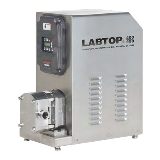
1.2 General Description LABTOP® Pump System features UNIBLOC®-PD and is a positive displacement rotary lobe pump. It is be supplied with a drive unit and controller within common Stainless Canopy (figure 1.0). UNIBLOC-PD can be supplied in the 5000 series with stainless steel bearing housing. -
Page 6: Limitation
1.2.1 Limitation The pump should be used for the duty for which it has been specified. The operating pressure, speed and temperature limits have been selected at the time of order and MUST BE ADHERED TO. These details are stated on the original order documentation. If not available, documentation may be obtained from your supplier by referencing the pump serial number and/or invoice number. -
Page 7: Safety
2.0 Safety 2.1 General This information must be read carefully before installation, operation or servicing. The safety instruction must always be available for the pump operator. The following symbols are used. WARNING: Indicates instructions that can affect personal safety if not followed. WARNING: Indicates electrical voltage instructions that can affect personal safety if not followed. - Page 8 If an integrated safety relief valve is installed, do not allow extended periods of recirculation through the valve. UNIBLOC-PUMP can either integrate a safety valve with the front cover, or supply one as a separate unit. Please contact your supplier.
-
Page 9: Installation
Caution must be taken when lifting the pump or pump unit. For all parts over 20kg we recommend the use of a lifting device or lifting arrangement when unpacking or moving. Check the weight guide in section 5.0 for details. See figure 3.0 and 3.1 for lifting guidance. LABTOP 200 Series LABTOP 300/400 Series Figure 3.0 Figure 3.1... -
Page 10: System Design
Protect the pump from unintended blockage from nuts, bolts, welding slag, etc, by installing a strainer. Also protect the pump from unintended operation against a closed valve by installing a safety/pressure relief valve. Strainers and relief valves can be provided by UNIBLOC-PUMP. ... - Page 11 Minimum flow rate required per seal: 1lpm (0.3gpm) or a rate that keeps seal temperature within 5°C (9°F) It includes shut-off valves and check valves in the system so that the flush can be turned off and stop unwanted substance from flowing in the wrong direction.
-
Page 12: Double O-Ring Seal Flushing/Cooling
3.3.2 Double O-Ring Seal Flushing/Cooling The flushing system may be arranged the same as the double mechanical seals, shown in figure 3.3.1 and 3.3.2. The double o- ring seals may also be lubricated with grease if the pump application justifies doing so. In this case, the seal flush chambers are filled through grease nipples with approved grease that is suitable for use with the pumped media. -
Page 13: Maintenance
Always use rubber gloves and protective goggles if handling caustic substances. The rotors and shaft seals in the pump have been selected for specific temperature and pressure conditions. Verify with UNIBLOC-PUMP or the documentation supplied with the pump that the operating parameters are not exceeded. -
Page 14: Maintenance Schedule And Recommended Spare Parts
When applications exceed constant service temperatures of 180 C (356 a vent and high temperature lubricant must be used. For such cases, contact UNIBLOC-PUMP or your supplier for an adequate service schedule. -
Page 15: Single Mechanical Seal
4.4.1 Single Mechanical Seal This type of shaft seal is used in most applications with products that have a viscosity of less than 1,000 cPs. The maximum rotational speed of this seal is 1500 rpm and the maximum service pressure is 13.5 bar (195 psig). The seal materials available are stainless steel, carbon, silicone carbide, and tungsten. -
Page 16: Unibloc 300-450 Single Mechanical Seal Removal
4.4.1.3 UNIBLOC 300-450 Single Mechanical Seal Removal Loosen the Stud Nuts (item 43 in Figure 4.4.1). Remove the Rotor Housing by pulling on the ports or by tapping gently with a rubber mallet. Do not rock the Rotor Housing back and forth excessively. The seals may break. The Seal Retaining Rings, the Bolts, the Stationary Seal Faces, and the Stationary Seal O-Rings will all come off with the Rotor Housing. -
Page 17: Flushed Single Mechanical Seal
4.4.2 Flushed Single Mechanical Seal The flushed single mechanical seal uses the same stationary mating ring, rotating seal nose ring, spring, and o-rings as the single mechanical seal discussed in section 4.4.1. The drive collar is different, however. The flushed single mechanical is not available for UNIBLOC 200-0, 200, 250, and 275. -
Page 18: Double Mechanical Seal
4.4.3 Double Mechanical Seal The flushed Double Mechanical Seal uses the same Stationary Seal Faces (primary & secondary) and Stationary Seal O-rings (primary & secondary) as the Single Mechanical Seals discussed in section 2.1.2. The Drive Collar and Rotating Seal Face are different, however. -
Page 19: Double Mechanical Seal Installation
4.4.3.2 Double Mechanical Seal Installation Place the Stationary Seal O-Rings (primary & secondary) in the rotor housing seal bores and the Flush Housings. Only lubricate these o-rings with water or alcohol. Push the Stationary Seal Faces (primary) into the rotor housing so that they seat flat with the step in the housing. -
Page 20: Unibloc 200-450 Seal Installation - Final Step
4.4.5 UNIBLOC 200-450 Seal Installation – Final Step See section 5.3 for torque limits. If not part of the shaft seal assembly, slide the plastic mounting sleeves over the splined ends of the shafts. Slide on the rotor housing (1) tap it with a rubber mallet to seat it properly on the dowel pins (20). -
Page 21: Pump Bearing Housing Service
180 C (356 F) a vent and high temperature lubricant must be used. For such cases, contact UNIBLOC-PUMP or an authorized service center for an adequate service schedule. Before proceeding with the following steps, DISENGAGE POWER TO THE MOTOR. If the pump is connected to piping, depressurize the system and close valves on both the suction and discharge sides to isolate the pump from the rest of the system. -
Page 22: Pump Assembly - Stainless Steel Rotors - Final Step
slide the bearings on so that the text on the bearing shoulder will make contact with the shaft shoulder. Use extreme caution to not damage the bearing components or the splined shaft end when using the hydraulic press. Place a non-metal object between the splined shaft end and the hydraulic press to prevent damage to the shaft. - Page 23 (12) and thread on the slotted nuts (13). Slide on the rotors (3b) and place a nonmetal object between the rotors to keep the shafts from turning. Tighten the nuts so that the shaft rotating torques shown in section 5.3 are achieved. Lock the nuts in place by bending the tabwasher into the slots in the nut.
-
Page 24: Troubleshooting
4.7 Troubleshooting PROBLEM POSSIBLE CAUSE SOLUTION Motor turning in wrong Reverse motor. No flow, but pump turns; pump does not direction Fill pipe and pump with liquid. prime Air pocket in pipe or pump. Check pipe fittings for leaks. Increase suction pipe diameter NPSHA too low. - Page 25 PROBLEM POSSIBLE CAUSE SOLUTION Cavitation. See C. Pump is noisy Liquid contains air. Check pump shaft seals for leaks. Check suction side pipe fittings for leaks. Increase NPSHA. Discharge pressure too high. Check suction and discharge piping for closed valves or obstructions.
-
Page 26: Technical Data
5.0 Technical Data 5.1 General Dimensions and Weights Drawing below shows overall dimensions for all models, 200-0 to 450 shown in Figure 5.1.1 and Table 5.1.2. LABTOP® Size inch (mm) inch (mm) inch (mm) 200-0 15.9 (405) 16.1 (410) 8.6 (219) Figure 5.1.1 15.9 (405) 16.4 (416) - Page 27 Spartan EP 150 121...152 (250...305) Shell Spirax S 75W90 -23...152 (-10...305) Sentinel S140 -26...288 (-15...550) Royal Purple Poly-Guard® FDA -26...165 (-15...330) Table 5.2.1 UNIBLOC MODEL APPROX. OIL CAPACITY, ml (oz.) 200, 250, 275 50 (1.7) 300, 350 150 (5.1) 400,450 350 (11.8) Table 5.2.2 Page 28 of 4...
-
Page 28: Tools And Torque Requirements
1) Bearing housing series 200 (Model 200-0 to 275) requires a socket removal/installation tool. Part# 6006-2 2) A plastic spline assembly sleeve is highly recommended when installing the rotor housing. UNIBLOC-PUMP can supply factory assembly sleeves. Please contact your pump supplier. Model 300/350 (Part# 6210) Model 400/450 (Part# 6220) 5.4 Rotor Clearances... -
Page 29: Pump Identification And Spare Parts
CLEARANCES FOR CLASS C STAINLESS STEEL CLEARANCES FOR CLASS D STAINLESS STEEL ROTORS, x0.01 mm (x0.001in.) ROTORS, x0.01 mm (x0.001in.) UNIBLOC POSITION UNIBLOC POSITION MODEL 8 & 10 9 &11 MODEL 8 & 10 9 &11 6-12 6-10 10-12 10-12 12-14 (2.3-4.7) (2.4-3.9) -
Page 30: Electronics/Operation
Product Description UNIBLOC®-PD 400 Size Stainless Pump Bearing Housing Standard Front Cover 316 Stainless Rotor Housing 1.5” T/C, Horizontal Mounting Class C 316L Stainless Rotors Standard Shafts, Drive Shaft in Top Position Single Mechanical Shaft Seal (SiC vs SiC) EPDM Elastomers 7.0 Electronics/Operation 7.1 Input Voltage ®... -
Page 31: Unit Operation
fuse, disconnect power to the unit and pull out the drawer using a small screwdriver blade. Insert a new identical fuse into the same slot and push the drawer in. Before turning the power back on, make sure the voltage selector is set to the correct voltage. LABTOP VOLTAGE FUSE P.N. -
Page 32: Digital Key Pad Operation
7.4.1 Digital Key Pad Operation Standard digital keypad (Figure 7.4.1.1) functions are explained below. Figure 7.4.1.1 Initiates forward run. If the pump is running in reverse when FWD is pressed, it will decelerate to zero speed, change direction, and accelerate to a preset speed. Initiates reverse run. - Page 33 Figure 7.4.2.1 Figure 7.4.2.2 Initiates forward run. If the pump is running in reverse when FWD is pressed, it will decelerate to zero speed, change direction, and accelerate to a preset speed. Initiates reverse run. If the pump is running in forward when REV is pressed, it will decelerate to zero speed, change direction, and accelerate to a preset speed.
- Page 34 PROG Toggle to Program Settings screen (see Figure 7.4.2.4) to view factory settings for unit. RAMP SET UP Toggle to Ramp Settings screen (see Figure 7.4.2.5) to change acceleration and deceleration ramp time. Figure 7.4.2.3 Figure 7.4.2.4 Figure 7.4.2.5 Page 35 of 4...
-
Page 35: Controller Settings And Update
Function Keys Function Key Emergency Stop Function Key Home Screen (Figure 7.4.2.1) Function Key Non-Functioning Function Key Factory Settings. Password Protected. System Settings. Password Protected Code 12345678 (Figure 7.4.2.6) Figure 7.4.2.6 7.4.3 Controller Settings and Update Adjustments may be made to the inverter which operates the function of the motor. For detailed instructions on Parameter adjustments, please refer to Control Panel Manufacturers Operation Manual. - Page 36 Page 37 of 41...
- Page 37 Page 38 of 41...
- Page 38 Page 39 of 41...
- Page 39 Page 40 of 41...
-
Page 40: Warranty
8.0 Warranty WARRANTY Unibloc Hygienic Technologies, LLC (“Unibloc”) warrants that its product will be free from defects in material and workmanship which results in noncompliance with the Specifications for such prod- uct. This warranty shall begin upon delivery and continue for a period of one (1) year from such date. - Page 41 Unibloc Hygienic Technologies, LLC 1650 Airport Road NW, Suite 110 • Kennesaw, Georgia 30144 • Tel 770-218-8900 E-Mail info@unibloctech.com www.unibloctech.com Copyright © 2022 Unibloc Hygienic Technologies, LLC Patented Designs Shown...
Need help?
Do you have a question about the LABTOP 200 Series and is the answer not in the manual?
Questions and answers