Table of Contents
Advertisement
Quick Links
Advertisement
Table of Contents

Related Manuals for Dahua ISC-D206


Summary of Contents for Dahua ISC-D206
- Page 1 Walk-through Metal Detector User's Manual V1.0.1...
-
Page 2: Foreword
Foreword General This manual introduces the functions and operations of the walk-through metal detector (hereinafter referred to as "the Device"). Models ISC-D206, ISC-D218 Safety Instructions Signal Words Meaning Indicates a high potential hazard which, if not avoided, will result in death or serious injury. - Page 3 ● All the designs and software are subject to change without prior written notice. The product updates might cause some differences between the actual product and the manual. Please contact the customer service for the latest program and supplementary documentation. ●...
-
Page 4: Important Safeguards And Warnings
Important Safeguards and Warnings This chapter describes the contents covering proper handling of the Device, hazard prevention, and prevention of property damage. Read these contents carefully before using the Device, comply with them when using, and keep the manual well for future reference. Operation Requirements ●... -
Page 5: Table Of Contents
3.3 Installing Device ..................................7 3.4 Multiple Walk-through Detectors Site Installation ....................11 3.5 Stabilizing Device ..................................11 4 Configuration ....................................... 13 4.1 ISC-D206 ....................................... 13 4.1.1 Configuration Panel ..............................13 4.1.2 Remote Controller ................................ 14 4.1.3 Device Operations ................................ 14 4.1.3.1 Function Description ............................ - Page 6 4.2.2 Remote Controller ................................ 21 4.2.3 Device Operations ................................ 21 4.2.3.1 Function Description ............................21 4.2.3.2 Password Setting ............................... 22 4.2.3.2.1 Login ................................22 4.2.3.2.2 Changing Password ..........................23 4.2.3.3 Setting Security Level ............................23 4.2.3.4 Setting Sensitivity ............................. 23 4.2.3.5 Setting Frequency .............................
-
Page 7: Overview
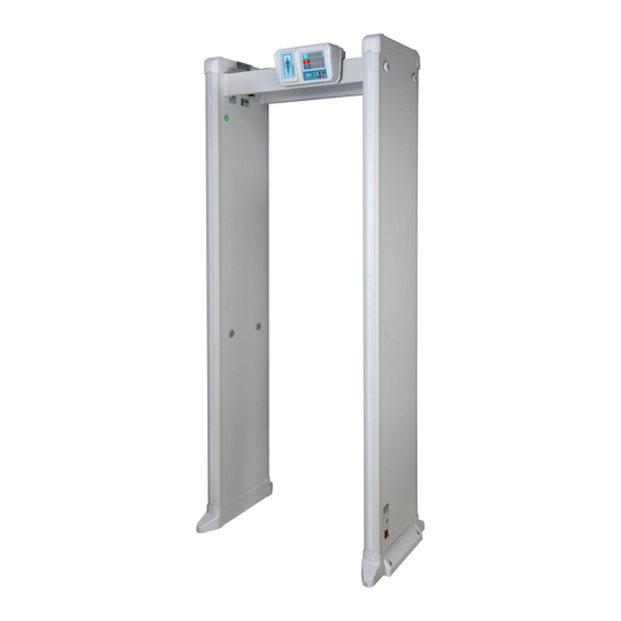
1 Overview 1.1 Introduction Walk-through metal detector is a high-performance security gate. The Device has high metal detection sensitivity, light weight, strong anti-interference, and stable performance. It uses high-strength special materials which are light-weighted and easy to transport and install. The Device has a modular design and is manufactured on the unified assembly lines, so it can ensure the good stability. -
Page 8: Technical Advantages
For ISC-206, only 6-zone is available. 1.3 Technical Advantages ● Start-stop Technology The IR units support manual start-stop technology for longer service life. ● Sensitivity Adjustable The sensitivity of each detection zone can be adjusted as needed to meet different sensitivity requirements of different zones. -
Page 9: Structure
2 Structure 2.1 Dimensions Figure 2-1 ISC-D206 (unit: mm) -
Page 10: Port
Figure 2-2 ISC-D218 (unit: mm) 2.2 Port... - Page 11 Figure 2-3 Port Table 2-1 Port description Name Description Power input port Connects to power cable to get power supply. Power supply switch Turn on or off the Device.
-
Page 12: Installation
3 Installation 3.1 Checklist After receiving the product, check against the table below. If there are any problems, contact the after-sales service personnel. Table 3-1 Checking list List Description Appearance Obvious damage Overall Packaging Accidental impact packaging Accessories ( see Table Complete or not 3-2) Appearance... -
Page 13: Installing Device
The distance in this section is the recommended distance. The actual installation distance depends on the installation site conditions. ● Keep away from moving metal objects Large moving metal objects should be kept 0.5 m to 2 m away from the detection door to avoid false alarms. - Page 14 Figure 3-2 Take out door panels Step 3 Take out the accessories from the box. Figure 3-3 Take out accessories Step 4 Prepare the door panels, beams, host box, and screws.
- Page 15 Figure 3-4 Prepare the parts and tools Step 5 Install the beams and the host box. Figure 3-5 Install the beams and the host box Step 6 Connect the detection wire on the host box to the left and right door panels, and then connect the host box and the door panel with the power cable (host box to door panel).
- Page 16 Figure 3-6 Connect the detection wire Step 7 Stand the Device up. Figure 3-7 Stand the Device up Step 8 Connect the power supply to the Device, and then turn on the power switch to start the Device.
-
Page 17: Multiple Walk-Through Detectors Site Installation
Figure 3-8 Stand the Device up 3.4 Multiple Walk-through Detectors Site Installation When installing multiple devices, space the devices at least 50 cm, and also space the device and X-ray larger than 50 cm. This recommended spacing can make the little metal objects (such as coin) detected. - Page 18 Tighten the fixing screws. Figure 3-10 Tighten the fixing screws...
-
Page 19: Configuration
4 Configuration 4.1 ISC-D206 4.1.1 Configuration Panel Figure 4-1 Configuration panel Table 4-1 Configuration panel description Name Displays number of passes. Displays alarm times. Working indicator light. When metal is detected, the alarm light on the door panel for the corresponding zone is on, and the indicator light grows green from red. -
Page 20: Remote Controller
4.1.2 Remote Controller You can set the parameters of the Device remotely through the remote controller. Install the batteries before using the remote controller. Figure 4-2 Remote controller Table 4-2 Operation description Name Description Changes the number or parameter value when setting a Up/Down parameter. -
Page 21: Password Setting
Function Parameter Description When multiple devices work simultaneously, set different frequencies for each device to Setting frequency reduce mutual interference. It ranges from 1 to 50, and 4 by default. Infrared start-stop function is designed for longer service life of the Device. You can set three modes of the light alarm: Start the front Setting infrared start-stop group, start the back group, and start both... -
Page 22: Setting Security Level
Figure 4-4 Configuration flow When 0000 0000 is displayed after power-on, press and hold Step 1 for 3 s. P 0000 is displayed. Step 2 Enter the old password (press to select the digit from 0 to 9 and press to set the next digit.), and then press C ---- is displayed. -
Page 23: Setting Frequency
Figure 4-7 Zones (ISC-D206) Step 2 Press to enter the sensitivity level. Figure 4-8 Setting sensitivity When both the defined threshold of security level and sensitivity are reached, an alarm will be triggered. For the details of sensitivity, see "4.1.3.3 Setting Security Level". -
Page 24: Setting Infrared Start-Stop
Figure 4-9 Setting frequencies 4.1.3.6 Setting Infrared Start-stop Infrared start-stop function is designed for longer service life of the Device. You can set three modes of the light alarm: Start the front group, start the back group, and start both groups. Step 1 Press to go to the setting interface, and then select R. -
Page 25: Setting Alarm Volume
Figure 4-11 Setting alarm tone 4.1.3.7.2 Setting Alarm Volume You can adjust the alarm volume. There are 3 levels: 0, 1, and 2. The bigger the number, the higher the volume. Step 1 Press to go to the setting interface, and then select y. Step 2 Press to enter the value. -
Page 26: Isc-D218
Step 2 Cover the infrared sensors with tapes, and then adjust the safety level and sensitivity until there is no false alarm caused by ambient environment. Step 3 Test the detection ability of each zone with a metal object. If the alarm is not triggered, adjust the frequency, and then do Step2 and Step3. -
Page 27: Remote Controller
Name – Save and exit Working indicator light. When metal is detected, the alarm light on the door panel for the corresponding zone is on, and the indicator light grows green from red. Program Power button 4.2.2 Remote Controller For details, see "4.1.2 Remote Controller". 4.2.3 Device Operations 4.2.3.1 Function Description Press... -
Page 28: Password Setting
Function Parameter Description The Device supports 72 scenarios, and every scene Setting scenarios corresponds to different sensitivity levels. It is 72 by default. Pillar light display Reserved function. Battery level Reserved function. The Device can adjust the Selecting automatic frequency frequency automatically. -
Page 29: Changing Password
Figure 4-16 Password setting failed 4.2.3.2.2 Changing Password Change the password regularly for the device safety. Step 1 Login the Device with the old password. Step 2 Press repeatedly until P 0000 is displayed. for 5 s, and C 0000 is displayed. Step 3 Press and hold Figure 4-17 Entering old password... -
Page 30: Setting Frequency
● 1R–6R: The detection sensitivity of right door (models with 12/18 zones). Figure 4-19 Zones (ISC-D218) Step 2 Press to enter the sensitivity level. Figure 4-20 Setting sensitivity When both the defined threshold of security level and sensitivity are reached, an alarm will be triggered. -
Page 31: Setting Infrared Start-Stop
Figure 4-21 Setting frequencies 4.2.3.6 Setting Infrared Start-stop Infrared start-stop is designed for longer service life of the Device. You can set four modes of the light alarm: Start the front group, start the back group, start both groups, and close both groups. to go to the setting interface, and then select 1R. -
Page 32: Selecting Automatic Frequency Hopping
Scenario Scenario Scenario Government Bureau of letters Shopping mall buildings and visits Drug treatment Airport Fire fighting center High-speed rail Ammunition Exam place station depot Gold and silver Railway station Courtroom jewelry Electroplating Bus station Food factory plant Wharf Die casting Bank. -
Page 33: Managing Zone
and 0 means disabled. It is 0 by default. Step 1 Press to go to the setting interface, and then select CF. Step 2 Press to enter the value. ● 0: Disabled ● 1: Enabled. Figure 4-24 Setting infrared start-stop 4.2.3.9 Managing Zone The door panel can be set to 18, 12 or 6 zones. -
Page 34: Setting Alarm Volume
Step 2 Press to enter the value. Figure 4-27 Setting alarm duration 4.2.3.10.3 Setting Alarm Volume You can adjust the alarm volume. It ranges from 0 to 99. The bigger the number is, the higher the volume is. Step 1 Press to go to the setting interface, and then select yc. -
Page 35: Faq
5 FAQ 1. Deal with the replaced spare parts. Contact our overseas maintenance points to check whether you need to send back the spare parts. 2. The Device cannot start. a. Check whether the power is switched on. b. Check whether the power cable is loose or broken. c. - Page 36 b. Check whether the ribbon cables of the alarm light are loose or broken. c. If the problem still cannot be solved, replace the host detector. 8. No alarm is triggered in zones. a. Adjust the sensitivity value higher b. Replace the host detector. c.
-
Page 37: Appendix 1 Cybersecurity Recommendations
Appendix 1 Cybersecurity Recommendations Cybersecurity is more than just a buzzword: it’s something that pertains to every device that is connected to the internet. IP video surveillance is not immune to cyber risks, but taking basic steps toward protecting and strengthening networks and networked appliances will make them less susceptible to attacks. - Page 38 6. Enable HTTPS We suggest you to enable HTTPS, so that you visit Web service through a secure communication channel. 7. MAC Address Binding We recommend you to bind the IP and MAC address of the gateway to the equipment, thus reducing the risk of ARP spoofing.
Need help?
Do you have a question about the ISC-D206 and is the answer not in the manual?
Questions and answers