Table of Contents
Advertisement
Quick Links
TRANSLATION OF THE ORIGINAL VERSION
Operating Manual
Tilting Spindle Moulder / Table Milling Machine
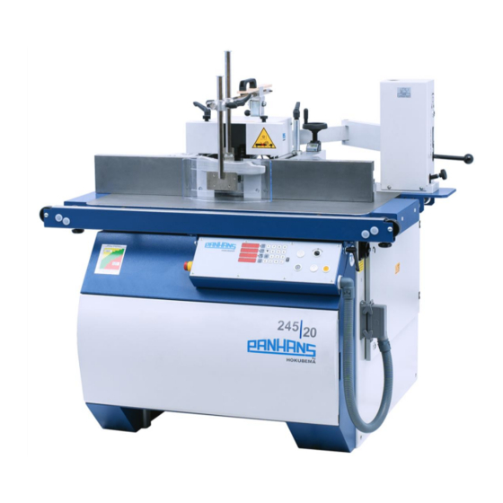
PANHANS 245|20
245|20
Machine-Type:
HOKUBEMA Maschinenbau GmbH
Graf-Stauffenberg-Kaserne, Binger Str. 28 | Halle 120
DE 72488 Sigmaringen | Tel. +49 07571 755-0
E-Mail:
info@hokubema-panhans.de
| Web:
https://hokubema-panhans.de
Advertisement
Table of Contents
Troubleshooting

Summary of Contents for HOKUBEMA PANHANS 245-20
- Page 1 TRANSLATION OF THE ORIGINAL VERSION Operating Manual Tilting Spindle Moulder / Table Milling Machine PANHANS 245|20 245|20 Machine-Type: HOKUBEMA Maschinenbau GmbH Graf-Stauffenberg-Kaserne, Binger Str. 28 | Halle 120 DE 72488 Sigmaringen | Tel. +49 07571 755-0 E-Mail: info@hokubema-panhans.de | Web:...
-
Page 2: Table Of Contents
Table of Contents Introduction ..............................7 Legal Notice ................................7 Illustrations ................................7 Symbols ................................7 General Symbols ..............................7 Symbols in Safety Instructions ..........................8 General ................................9 Intended Use................................. 10 Target Group and Previous Experience......................... 10 Requirements for the Operators .......................... 10 Accident Prevention .............................. - Page 3 Hazardous Areas ..............................22 Machine Data ............................... 23 Technical Specifications ............................23 Working Area ................................ 24 Emission Levels ..............................24 5.3.1 Noise Information ................................24 5.3.2 Noise Emission Values ..............................24 Dimensions ..............................25 Front View................................25 Top View ................................25 Installation and Connection..........................
- Page 4 13.2.3 Calibrating the Tilt Axis Indicator ............................. 38 13.3 Height Adjustment ..............................39 13.3.1 Absolute Positioning ................................ 39 13.3.2 Incremental Positioning ..............................39 13.3.3 Height Adjustment in Manual or Inching Mode ....................... 39 13.3.4 Height Adjustment via Target Value Input ........................40 13.3.5 Calibrating the Height Axis Indicator ..........................
- Page 5 Troubleshooting ............................57 17.1 Error Messages of the Control Unit ........................57 Maintenance and Inspection ........................58 18.1 Maintenance of the Milling Fence ........................58 18.2 Maintenance of the Tenoning and Slotting Device Type 1376 (Option) ............... 58 18.3 Maintenance Plan ..............................59 18.4 Readjust the Motor Brake .............................
- Page 6 Figure 20: Clamping surfaces and locking ......................35 Figure 21: Tool tray for pin spanner ........................36 Figure 22: Operating elements of the positioning control ..................37 Figure 23: Calibrate tilt indicator .......................... 38 Figure 24: Calibrate height indicator ........................40 Figure 25: Calibrate cutter height with Zeromaster ....................
-
Page 7: Introduction
Legal Notice All contents of these operating instructions are subject to the rights of use and copyright of Hokubema Maschi- nenbau GmbH. Any reproduction, modification, further use and publication in other electronic or printed media, as well as their online publication, requires the prior written consent of Hokubema Maschinenbau GmbH. -
Page 8: Symbols In Safety Instructions
Symbols in Safety Instructions Symbol Safety Instruction General danger symbol, which requires the highest attention! Failure to observe may result in damage to the equipment, serious injury or even death. Warning of possible danger from forklift traffic! Non-observance may result in life-threatening injuries. Warning indicates a possible hazard under suspended loads! Non-observance may result in life-threatening injuries. -
Page 9: General
General The PANHANS type 245|20 is a universal tilting spindle moulder with height and tilt adjustable milling arbor, two directions of rotation, quick tool change device, adjustable speed as well as separately adjustable total and partial fence. • The milling spindle is driven by a three-phase motor. •... -
Page 10: Intended Use
Intended Use The PANHANS 245|20 tilting spindle moulder is used exclusively for machining materials for which the milling cutter used is suitable (e.g. wood, chipboard, veneer). The machines are not suitable for milling metal resp. plas- tic and waste wood which could contain nails, screws and other metal parts. The machine may only be operated on a firm, level surface with a minimum load-bearing capacity of 1,000 kg/m. -
Page 11: Accident Prevention
Accident Prevention To avoid accidents, the following rules must be observed for operation: • Prevent unauthorized persons from gaining access to the machine. • Keep unauthorized persons away from the danger areas. • Repeatedly inform present other persons about existing residual risks (see section 4.2.3). •... -
Page 12: Included Components
Further optional table systems, milling fences, tool quick-change systems, milling spindles and arbors, tenoning, slotting and feed units and other special accessories can be found in chapter 20. In addition, you can order accessories and spare parts in our online shop www.hokubema.com. BA_PH_245-20_EN_15-22.docx... -
Page 13: Safety
Safety Basic Safety Instructions Woodworking machines can be dangerous if used improperly. Therefore, observe the safety instructions listed in this chapter and the accident prevention regulations of your employer's liability insurance association! The manufacturer accepts no liability for damage and malfunctions resulting from failure to observe these operating instructions. -
Page 14: Permissible Tool Dimensions
4.2.2 Permissible Tool Dimensions Spindle Ø Maximum clamping length Milling cutters Tenoning and slotting tools 30 mm 140 mm 80 - 250 mm max. 300 mm 40 mm 160 mm 80 - 250 mm max. 350 mm 50 mm 160 mm 80 - 250 mm max. -
Page 15: Observe The Environmental Protection Regulations
Electrical equipment must be maintained and cleaned regularly. Pay attention to the danger of crushing on workpiece guides and moving machine parts. Make sure that no unauthorised persons are in the area of the machine. Be aware of the risk of injury from flying tool parts in the event of tool breakage. Therefore wear protective goggles. -
Page 16: Personnel Selection And Qualification - Basic Duties
Spare parts must meet the technical requirements specified by the manufacturer. The exclusive use of original spare parts ensures this. Therefore, only use original spare parts from the manufacturer. Observe the fire alarm and firefighting possibilities. Make the location and operation of fire extinguishers (fire class ABC) known. -
Page 17: Normal Operation
4.3.2 Normal Operation Guards: Take measures to ensure that the machine can only be operated in a safe and functional condition. Only operate the machine when all guards and safety-related devices such as - detachable guards (e.g. tool covers and fence covers), - emergency stop system, sound insulation, suction device etc. -
Page 18: Special Work Within The Scope Of Maintenance Work As Well As Troubleshooting In The Workflow
4.3.3 Special work within the Scope of Maintenance Work as well as Troubleshooting in the Workflow Observe maintenance and inspection activities prescribed in the operating manual! These activities, as well as all other repair work, may only be carried out by qualified personnel! For all work concerning operation, production adjustment, conversion or setting of the machine and its safety-related equipment as well as maintenance and repair, observe switch-on and switch-off procedures according to the operating manual and instructions for maintenance work! -
Page 19: Tool Handling
4.4.4 Tool Handling Tools must be handled with care and tool transport equipment must be used whenever possible. 4.4.5 Tool Clamping Use suitable devices, e.g. setting gauges, to clamp the tool when the machine is at a standstill. To keep the gap between the spindle and the table as small as possible, the matching table insert rings must be used or the optional table slide plate (see ... - Page 20 4.4.9.1 Milling at the fence, where the machining extends over the full workpiece length With workpieces that usually have a right-angled cross-section over their entire length, this machining operation is carried out by using a milling fence. Since the fence rulers are at a 90° angle to the table top, the workpiece can be guided at right angles along the fence rulers.
-
Page 21: Use Of Work Devices With Protective Function
• For accident-free insertion milling of long and short parts (infinitely adjustable from 0 to 1500 mm). 4.4.13.5 Power Feeders • For a safe workpiece feed (refer to section 16.13). You can find further accessories in chapter 18 and in our online shop https://www.hokubema.com BA_PH_245-20_EN_15-22.docx... -
Page 22: Hazardous Areas
Hazardous Areas Hazard Area/Action Risk Avoidance Cutting Hazard At the tool • When changing • Wear gloves when changing Mild to severe inju- ries to hands and the cutter head the cutter. • In case of contact with • Keep hands out of the danger fingers the rotating cutter zone. -
Page 23: Machine Data
Suction Nozzles: 2 pieces, Ø 120 mm Net Weight: approx. 800 kg Space Requirement: 1200 x 1400 mm Nameplate: Manufacturer: HOKUBEMA Maschinenbau GmbH Graf-Stauffenberg-Kaserne Binger Str. 28 | Halle 120 DE-72488 Sigmaringen (Germany) Tel.: +49 (0) 7571 / 755-0 Fax: +49 (0) 7571 / 755-2 22... -
Page 24: Working Area
Working Area The working area designates the position from which the machine is operated. Working area Figure 3: Working area Emission Levels 5.3.1 Noise Information The values given are emission levels and therefore do not necessarily represent safe workstation values at the same time. -
Page 25: Dimensions
Dimensions Front View 1145 1000 Figure 4: Dimensions - front view Top View 1100 Figure 5: Dimensions - top view BA_PH_245-20_EN_15-22.docx... -
Page 26: Installation And Connection
and Connection 7 Installation Check Delivery Conditions Check the consignment for completeness and possible transport damage. In case of transport damage, please keep the packaging and inform the shipping company and the manufacturer immediately! Later complaints can- not be accepted. Transport to the Installation Site The machine is delivered on a transport pallet and is bolted to the bottom of the pallet. -
Page 27: Temporary Storage
Dispose of the packaging material in an environmentally friendly way! Do not use nitro thinner for cleaning. Painted surfaces of the machine can be damaged. Fire hazard! Do not smoke and do not light an open fire. Temporary Storage If the machine is not put into operation immediately after delivery, it must be stored carefully in a protected place. -
Page 28: Connecting The Extraction Unit
Connecting the Extraction Unit The machine must be connected to an effective extraction sys- tem on-site. The two extraction nozzles (1) and (2) each have an outer diameter of 120 mm. For transport reasons, the lower extraction socket in the stand is mounted with the connection facing inwards (1a). -
Page 29: Electrical Connection
Electrical Connection The electrical connection must be carried out by an authorised electrician! The electrical circuit diagrams are located in the control cabinet. Please observe the specified nominal voltage 400 VAC / 50 Hz (3 phases / N / PE)! The connection to the mains (3 phases) is made via the terminal strip in the terminal box on the right side of the machine. -
Page 30: Components And Control Elements
Components and Control Elements Machine Figure 11: Components and Control Elements Pos. Description Pos. Description Main switch position Main fence handwheel adjustment Milling spindle Machine table Control panel with control unit Table insert rings (table slide plate optionally) Emergency stop button Tilt axis indicator Milling fence type 216 Height axis indicator... -
Page 31: Control Panel
Control Panel "0! – Figure 12: Control panel Pos. Description Pos. Description Tilt axis indicator Clear entry – Height axis indicator (absolute) Manual / inching mode in negative direction Height axis indicator (incremental) Manual / inching mode in positive direction Speed indicator Positioning enable (deadman function) ... -
Page 32: Commissioning
Commissioning Before commissioning, carefully read and observe this manual and the safety instructions in chapter Before switching on, make sure that • the cutter is firmly and securely clamped, • the machine table and fence are clean and free of objects, •... -
Page 33: Emergency Stop Function
10.2 Emergency Stop Function In case of danger or malfunctions during operation, the machine can be stopped quickly and reliably by pressing the emergency stop button (4) on the control panel (see Figure 11). Before restarting the machine, the emergency stop button must be unlocked again. ... -
Page 34: Tool Change
Tool Change 12.1 With Quick Clamping Device (Standard) The tools used on the machine must comply with EN 847-1! Wear cut-resistant protective gloves when changing tools! • Before changing the tool, switch off the spindle drive with the button (see ... -
Page 35: Changing Procedure
12.2.1 Changing Procedure Before changing the tool, switch off the spindle drive with the button 1. First remove the supplied SW8 pin spanner from the tool tray (shown in Figure 21). 2. Press the emergency stop button (4) and leave it locked. 3. -
Page 36: Figure 21: Tool Tray For Pin Spanner
12.2.1.1 Security check for pin spanner For safety reasons, the SW8 pin spanner must be re- turned into the tool tray on the right of the machine, after the HSK 80 milling arbor has been clamped (the tray also serves to store the optional “Zeromaster”). A limit switch in the tool tray checks that the spanner has been properly deposited. -
Page 37: Positioning The Spindle Height And Tilt
Positioning the Spindle Height and Tilt The height and tilt axes are positioned via the positioning control integrated in the control panel. All positions and the set speed are visualised via LED indicators. Pos. Description Tilt axis indicator Height axis indicator (absolute) Height axis indicator (incremental) Speed indicator Tilt axis selection... -
Page 38: Tilt Adjustment Via Target Value Input
Continuously position to desired angle (manual mode): a) Press the buttons “P” and “+” simultaneously → positive adjustment until the “+” button is released b) Press the buttons “P” and “–” simultaneously → positive adjustment until the “–” button is released Position in 0.1°... -
Page 39: Height Adjustment
13.3 Height Adjustment The positioning of the milling spindle height is done either in manual resp. inching mode or continuously by prior entry of target values via the number entry field “N”. The height can be positioned either in absolute mode or in incremental mode. Note: The two display windows for absolute and incremental measurement can indicate different values. -
Page 40: Height Adjustment Via Target Value Input
13.3.4 Height Adjustment via Target Value Input Please note: Only one dimension (absolute or incremental) can be set at a time! • First activate the entry field for the height axis via the “TA2” resp. “TA3” button → LED next to “TA2” resp. “TA3” lights up. •... -
Page 41: Calibrate Cutter Height With Zeromaster (Option)
13.3.6 Calibrate Cutter Height with Zeromaster (Option) With the optional PANHANS "Zeromaster" calibrator, the display "A3" is semi-automatically calibrated to the incremental zero point of the upper edge of the cutter (related to the upper edge of the table top). This calibra- tion procedure does not refer to the spindle, but always to the currently clamped cutter. -
Page 42: Milling Fences
Milling Fences 14.1 Placing and Aligning the Milling Fence In order to place the fence on the table top and to align it parallel without the need for further tools, all fence types are equipped with a dovetail receptacle (S) on the under- side and two spring-mounted centring pins (Z). -
Page 43: Functions And Adjustment Of The Milling Fences
14.2 Functions and Adjustment of the Milling Fences Two different fence types are available for the 245|20 tilting spindle moulder: • Fence Type 216 (standard) → Total fence is manually adjustable via handwheel and partial fence via adjusting screw. → The handwheel for the total fence is equipped with a digital, battery-operated position indicator. →... -
Page 44: Figure 32: Locking Bolt Of Type 216
Fence plate adjustment Loosen the star grip (8) and push the fence plate (1) to the desired position. Then retighten the star grip (8). Always adjust the plates so that they cover as much of the tool as possible without touching it. Folding up the protective hood Before the protective hood (12) of the fence can be folded up, the locking bolt (V) at the rear left must be unlocked by pulling it out (see... -
Page 45: Fence Type 204 (Option)
14.2.2 Fence Type 204 (Option) With type 302, the total and partial fence are manually adjustable. To adjust the complete fence, release the two quick-release levers (3) and (6) and adjust the fence via handwheel (2) and/or (5). Afterwards, the two quick-release levers must be re-tightened. -
Page 46: Swivel-Away Device Type 219 (Option)
Lifting off and removing the fence Increased risk of accidents due to the high weight of the fence! Lifting and placing the fence should be done by at least two people or with a suitable hoist (e.g. an indoor crane)! •... -
Page 47: Handwheel Adjustment
14.4 Handwheel Adjustment The fence type 216 is equipped with the digital handwheel “DE10”. Via the LCD display, the total fence position can be read off directly at the fence with an accuracy of 0.1 mm. Absolute / incremental measurement switchover: •... -
Page 48: Ring Fence Tapoa 1639
14.4.2 Ring Fence TAPOA 1639 The supplied TAPOA 1639 ring fence is used for accident-free milling of curved workpieces by means of a clamp- ing template. It is suitable for spindle diameters of 30, 35, 40 and 45 mm and for tool diameters up to 160 mm. The ring fence can be quickly attached to the milling table and is easy to adjust. -
Page 49: Protection And Pressure Devices
Protection and Pressure Devices If no power feeder is used for milling, a protection and pressure device must be used. 15.1 TYPE 1629 GAMMA V (Standard) The standard protection and pressure device type 1629 GAMMA V is suitable for all milling fences described in section ... -
Page 50: Optional Components
Optional Components 16.1 Integral Fence System The milling fences 301, 302, 311 and 320 can optionally be equipped with integral fence plates. These can be mounted without tools and in just a few steps instead of the standard cast fence plates. The swivelling guide fingers integrated in the fence plates al- ways ensure a gap-free guide surface and optimum tool cov- erage for all milling work. -
Page 51: Safety Rulers For The Milling Fence
16.3 Safety Rulers for the Milling Fence The optional safety rulers serve as a continuous guide between the two fence plates. The set consists of: • 2 safety rulers 260 x 6 mm • 3 safety rulers 260 x 3 mm, •... -
Page 52: Extendable Frame Support
16.6 Extendable Frame Support The table top with dimensions 1100 x 760 mm can optionally be equipped with an extendable frame support (instead of the rigid standard frame support). • Toral length approx. 1375 mm • Extension depth approx. from the centre of the milling spindle. -
Page 53: Tenoning And Slotting Device Type 1376
16.9 Tenoning and Slotting Device Type 1376 The tenoning and slotting device 1376 is used for tenoning and slotting on the tilting spindle moulder. It is usually already factory-fitted to the table top of the machine. The integrated mitre fence can be swivelled by 60° to both sides and enables angular cuts from 30°... -
Page 54: Adaptation To The Machine Table (Only Required For Retrofitting)
16.9.3 Adaptation to the Machine Table (only required for retrofitting) Mount the tenoning and slotting Tischplatte Table top device as close as possible to the milling arbor. The diameters of the largest and Fräsdorn smallest cutter heads used are deci- Milling arbor sive for the distance to the milling arbor. -
Page 55: Cross-Cut Fence Las-M
16.11 Cross-Cut Fence LAS-M Right-hand version for system tools with a use- ful length of 1750 mm. Ideal for machining workpieces in pairs. Slider system with multiple stop and 3 adjust- ing rings for cross-cut positioning with a split- ter tongue. Article number see section ... -
Page 56: Power Feeders
16.13 Power Feeders For safety reasons, a power feeder should be used whenever possible. Generally applies: Always adjust the power feeder so that the workpiece is guided safely along the fence. Set the unit at an angle of approx. 5° to the feed direction and keep the opening to the fence as small as possible. Figure 57: Power feeder type PV84 Figure 58: Power feeder type Variomatic 4N •... -
Page 57: Troubleshooting
Troubleshooting Proceed systematically when searching for the cause of a malfunction. If you are unable to find the fault or to remedy the malfunction, contact our customer service department (phone number: 0049 7571 / 755 - 0). Before you call us, please follow these steps: •... -
Page 58: Maintenance And Inspection
Maintenance and Inspection Before any maintenance and inspection work is carried out, chapter 4 "Safety" must be read carefully and observed! Operational malfunctions caused by insufficient or improper maintenance can result in very high repair costs and long machine downtimes. Regular maintenance is therefore essential. •... -
Page 59: Maintenance Plan
18.3 Maintenance Plan Activity Cleaning the machine Check that the extraction system is fully functional before starting work. Inspect electrical equipment and components for externally visible damage and have this repaired by a qualified electrician if necessary. Check drive belt condition. Check drive belt tension. -
Page 60: Readjust The Motor Brake
18.4 Readjust the Motor Brake The spindle moulder is equipped with a mechanical motor brake. If the machine no longer comes to a standstill within 10 seconds when braking, the motor brake must be adjusted. Switch off the machine during maintenance and repair work and secure it against being switched on again unexpectedly! Lock the main switch with a padlock! Procedure:... -
Page 61: Change And Tighten The Drive Belt
18.5 Change and Tighten the Drive Belt Switch off the machine during belt replacement and tightening and secure it against unintentional restarting! Lock the main switch with a padlock! The drive belt should be replaced in the event of excessive wear, frayed flanks, traces of oil, porosity or if cross- sectional fractures are present. -
Page 62: Lubrication Instruction
Lubrication Instruction The machine has been extensively test-run at the factory and is lubricated ready for operation. Relubrication before commissioning is therefore not necessary. For subsequent lubrication, use only special grease, e.g.: • PANHANS ZET-GE-MSO • ARCANOL BN 102 • CALYPSOL H 442 B •... -
Page 63: Lubrication Plan
19.2 Lubrication Plan Figure 67: Central lubrication Figure 66: Lubrication points on the machine To keep the machine parts always clean and in perfect condition, excess and/or old grease must be wiped off at the outlet points of all existing grease nipples and other guiding elements! Standard Version Pos. -
Page 64: Options And Accessories
In the following tables you will find available options and accessories to upgrade your machine. You can find general spare parts in our online shop on https://www.hokubema.com. Use only the tools, accessories and spare parts specified by the manufacturer. The use of other tools, accessories or spare parts may cause injury to persons and damage to the machine. -
Page 65: Milling Fences
Continuation „Table Systems“ Article Description Art. No. TABLE EXTENSION For table top 1340 x 800 mm: Finely planed cast iron table top as ex- ONE-SIDED RIGHT tension on the right side of the standard machine table, thus total 4217 length = 1950 mm, with smooth-running frame support approx. 970 mm, extendable to the front. -
Page 66: Milling Spindles And Arbors
20.4 Milling Spindles and Arbors Article Description Art. No. MILLING SPINDLE Ø 1 ¼" Not interchangeable, dynamically balanced for optimum concen- tricity, clamping height 140 mm with cutter arbor rings and cutter 4153 quick-clamping device via Allen key with anti-rotation lock, instead of 30 mm standard milling spindle. -
Page 67: Power Feeders And Consoles
400 g grease cartridge, output pressure max. 350 bar. SPECIAL VOLTAGE Instead of the standard 400 V voltage. 4601 220 V/50 HZ, MAX. 7.5 KW You can find more spare parts in the online shop on https://www.hokubema.com. BA_PH_245-20_EN_15-22.docx... -
Page 68: Disassembly And Scrapping
Disassembly and Scrapping When dismantling and scrapping the machine, the current EU regulations or the respective regulations and laws of the country of operation, which are prescribed for proper dismantling and disposal, must be observed. The aim is to dismantle the machine and its various materials and components properly, to recycle all possible parts and to dispose of non-recyclable components in the most environmentally friendly way. -
Page 69: Eu - Declaration Of Conformity
EU - Declaration of Conformity in accordance with the EU Machinery Directive 2006/42/EC Annex II A The manufacturer, HOKUBEMA Maschinenbau GmbH Graf-Stauffenberg-Kaserne Binger Str. 28 | Halle 120 Phone: +49 (0) 7571 / 755 - 0 DE 72488 Sigmaringen (Germany)
Need help?
Do you have a question about the PANHANS 245-20 and is the answer not in the manual?
Questions and answers