
Subscribe to Our Youtube Channel
Related Manuals for Interfacom TAXITRONIC TC60

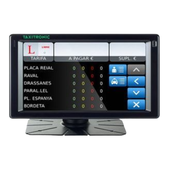
Summary of Contents for Interfacom TAXITRONIC TC60
- Page 1 INTERFACOM, S.A INSTALLATION MANUAL TAXITRONIC TC60-TV60 TC60_Install_Manual_en_015.doc 08/05/2013...
-
Page 2: Table Of Contents
TC60-TV60 INSTALLATION MANUAL INTERFACOM, S.A INDEX Introduction ........................4 Mounting ........................4 2.1. Mounting TC60 ..................... 4 2.1.1. Placing of TC60 ......................4 2.2. Mounting TV60 ..................... 4 2.2.1. Placing of TV60 ......................5 2.3. Electrical installation ..................... 5 2.4. - Page 3 INTERFACOM, S.A DRAWINGS LIST Drawing 1 TV60 bracket assembly Drawing 2 TV60 unit drawing Drawing 3 TC60 connectors Drawing 4 Installation drawing (*1) Drawing 5.1 TC60 Plastic sealing Drawing 5.2 TV60 Plastic sealing Drawing 6.1 TC60 cable sealing Drawing 6.2...
-
Page 4: Introduction
INTERFACOM, S.A 1. INTRODUCTION This document describes the installation and parametrization of TAXITRONIC TC60/TV60. 2. MOUNTING 2.1. MOUNTING TC60 TC60 mounting is prepared for 4 adhesive supports, which can optionally be fixed with screws, and two cable ties. The supports must be fit rigidly, to avoid vibrations. -
Page 5: Placing Of Tv60
INTERFACOM, S.A Isopropilic alcohol (If there are previous installation or tariff seals to be removed) The orientation of TV60 is fixed by screwing the two Allen screws on the sides (points B and C on drawing 2). The central screw which touches directly on the support ball is not... -
Page 6: Characteristics
INTERFACOM, S.A 2.4. CHARACTERISTICS The dimensions of the units are: TC60 174x140x45 mm (length x width x heigth) Weigth 520 g TV60 178x70x100 mm Weigth 630 g TC60 and TV60 are designed and certified to operate in an environment of electromagnetic class E3 (instruments powered by a vehicle battery) and in a mechanical environment class M3 (high and very high vibration level, such as in all type of vehicle). -
Page 7: Installation Recommendations
INTERFACOM, S.A 2.5. INSTALLATION RECOMMENDATIONS Disconnect the battery positive contact until the whole electrical installation is finished. Any work on the terminal or accessory must be done with the device disconnected from the battery or without the general fuse. Always use the positive and negative directly from the battery, to get a more filtered power supply and avoid false contacts. -
Page 8: First Time Turn On
INTERFACOM, S.A 3. FIRST TIME TURN ON Turn on the unit by pressing on the touchscreen. The unit starts, showing a progress bar. Finally you get a screen with the message “ENTER A VALID USB” Connect the USB stick with installer key to the USB connector A screen requests for the installer password Enter the password and press OK. -
Page 9: Configuration Parameters
INTERFACOM, S.A 3.1. CONFIGURATION PARAMETERS When in the main Manufacturing screen, press “Configure” The application configuration parameters will open. These parameters are not metrologic, so they are not subject to legal sealing. This can also be accessed with an installer magnetic card. - Page 10 INTERFACOM, S.A Audio DspEchoCancel Activates echo cancellation Normally use this activated TC60 External mic connected to TC60 Micr Choose the used microphone TV60 Internal TV60 mic Merc Specific Mercedes microphone TC60 External loudspeaker Choose the used loudspeaker TV60 Internal TV60 loudspeaker...
- Page 11 INTERFACOM, S.A In case of vehicles with excessive echo, which can not be solved with the previously explained parameters, it is also possible to adjust the microphone gain to reduce the echo. Echo is not solved by increasing the volume: On the opposite, it is solved by lowering the output volume or lowering the microphone gain.
- Page 12 INTERFACOM, S.A GPRS GSM GPRS APN Identification of the GPRS network Central Port UDP Port of the central programm GPRS Sufix, used as a second part of the Your network support will give you this GPRS Sufix GPRS user. data if needed...
- Page 13 INTERFACOM, S.A RT Params Name Name of license owner Licence License number Plate Number Plate number Fiscal ID Car ID ID of the car in the Radiotaxi Driver 1..4 Driver codes of the 4 drivers Company Company code Used by the Prima application...
- Page 14 INTERFACOM, S.A Tickets These screens are used to set all the data related to tickets. The data are: Ticket Headers 6 ticket headers Ticket Footers 8 ticket footers 4 Manual Extras Extras text Extras text in the tickets 1 Automatic Extra...
- Page 15 INTERFACOM, S.A Installation Operator Installer who installs the device Factory Code of the workshop Date Installation date Format YYYYMMDD Bat. Calibration Battery calibration Touch Calibr. Touchscreen calibration EMV Type Type of EMV payment Serial port where PinPad is EMV SerialPort...
- Page 16 INTERFACOM, S.A Battery calibration This operation is only necessary in case that you have formated the board. Is not neccesary if you change the battery. To calibrate the battery: Open the TC60 box so you can access the battery Enter Bat. Calibration Measure the Battery voltage with a tester.
- Page 17 INTERFACOM, S.A Hardware test Press HW Test. These screens allow to test the TC60 and TV60. See the summary table on Annex II to have all the verification options It is necessary to test the correct connexion of all the elements and peripherals connected to the TC60.
-
Page 18: Switch To Normal Mode
INTERFACOM, S.A 3.2. SWITCH TO NORMAL MODE Before installation is complete, change the working mode to Normal before the next restart of the unit. Select “Normal” in the “Next Boot” frame. Then you can turn the TC60 off. At next startup,... -
Page 19: Taximeter Configuration
INTERFACOM, S.A 4. TAXIMETER CONFIGURATION With the TC60 in Normal mode, and with the taximeter in Free, open the sealed tariff cover and connect a USB memory containing a valid tariff and installer key. The screen will display the tariffs present in the USB. Select the adequate one. -
Page 20: Pull-Up Configuration
INTERFACOM, S.A Adjustment of the trigger value for adequation to the car signal. The trigger value counts from the center value of the signal Modify Trigger value. The default 1000 mV is compatible with most cars. Change only if the signal shape is not standard, and test until an adequate value is found. -
Page 21: Calculation Of The K Constant
INTERFACOM, S.A 4.1.2. CALCULATION OF THE K CONSTANT To calculate the value of the K constant On the main taximeter configuration screen, press on button K Press on the field “PULSES” to start the counting of the number of impulses... -
Page 22: Setting The Calendar - Clock
INTERFACOM, S.A 4.3. SETTING THE CALENDAR - CLOCK The date / time of the taximeter is updated with the following process: Press on the CLOCK button The date field is displayed in format YYMMDD (Year Month Day) Press OK Enter the current time in format HHMMSS (Hours Minutes Seconds) Press OK again to go to the main screen and record the configured data. -
Page 23: Sealing
INTERFACOM, S.A 5. SEALING TC60 - Two sealing options are possible: - OPTION A: Plastic seal (Drawing 5.1) A housing for a plastic seal is used. It is not possible to access the sealed screw without breaking the seal. - OPTIÓN B: Cable sealing (Drawing 6.1) For this type of sealing, an anti-turn angle and a screw with a hole are used. -
Page 24: Maintenance
INTERFACOM, S.A 6. MAINTENANCE The TC60 has a utility to test the unit functioning once installed, be it locally or remotely, and for the update of its software. 6.1. HARDWARE TEST In case any element in the units is not working correctly, a complete hardware test can be done. -
Page 25: Repairs
The installation register has to be filled and sent again to Interfacom. It is not possible to do substitutions of boards, only complete units. Only Interfacom can have access to opening the units and act on the boards. The seals which keep the integrity of the electronics, with the logo TAXITRONIC, must never be opened by unauthorised personnel. -
Page 26: Software Update
INTERFACOM, S.A 6.5. SOFTWARE UPDATE In case it is necessary to update the software, the installer will get an USB device with the updates to the last software version. The process is the following: 6.5.1. TC60 IN NORMAL MODE In case the unit is started in normal user mode, it is necessary to switch to installing mode. - Page 27 INTERFACOM, S.A Connect the USB memory with the update files to a USB connector. The available update files are displayed. The name of each one indicates the origin version and the destionation version. Select the adequate update file and press Accept The unit will return to the start screen Press OFF to switch the unit OFF.
-
Page 28: Annex I
INTERFACOM, S.A ANNEX I TC60 HARDWARE TEST IO (INPUT/OUTPUTS) MEANING EXPLANATION automatic An automatic test is started, and the result on each Pin test is tested. If any of the pins does not work correctly, it is displayed onscreen. Once the test is finished, the circle... - Page 29 INTERFACOM, S.A External battery Displays the voltage and charge status of the external voltage level battery (car) and internal battery. It also displays the temperature of the internal battery. Internal battery Displays the voltage voltage level levels Internal battery temperature...
- Page 30 INTERFACOM, S.A The car has to be in the open for some minutes DATE before the measure is reliable. Select GPS. The GPS data are displayed. If TIME ZONE nothing is detected, the data will be displayed as Displays the GPS LATITUDE 0, except possibly time and date.
- Page 31 INTERFACOM, S.A MEANING EXPLANATION Bluetooth status and (Not currently implemented) Pressing this button the detected device is functioning status displayed, or an error message is displayed. SRAM MEANING EXPLANATION Pressing the button starts the automatic test. Verifies the correct functioning of the The test result is finally displayed For this test to be reliable, the TC60 must have been for some seconds without power supply.
- Page 32 TC60-TV60 INSTALLATION MANUAL INTERFACOM, S.A TV60 HARDWARE TEST SCREEN MEANING EXPLANATION Press T for the touchscreen test or C for the color test Color test: 4 color bars are displayed, with red, green, blue and black colors. Verifies the display Check that the 4 bars are displayed with correct gradual colors.
- Page 33 INTERFACOM, S.A Checks the Cover the TV60 light sensor to check that the detected value goes to the low functioning of the values. Point a light at the sensor to check that the detected light value goes light sensor...
Need help?
Do you have a question about the TAXITRONIC TC60 and is the answer not in the manual?
Questions and answers