Table of Contents
Advertisement
Quick Links
Advertisement
Table of Contents

Related Manuals for ASROCK H310M-G/M.2


Summary of Contents for ASROCK H310M-G/M.2
- Page 2 (including damages for loss of proits, loss of business, loss of data, interruption of business and the like), even if ASRock has been advised of the possibility of such damages arising from any defect or error in the documentation or product.
- Page 3 You are also entitled to have the goods repaired or replaced if the goods fail to be of acceptable quality and the failure does not amount to a major failure. If you require assistance please call ASRock Tel : +886-2-28965588 ext.123 (Standard International call charges apply) he terms HDMI™...
-
Page 4: Table Of Contents
Expansion Slots (PCI Express Slots) Jumpers Setup Onboard Headers and Connectors Chapter 3 Software and Utilities Operation Installing Drivers A-Tuning ASRock Live Update & APP Shop 3.3.1 UI Overview 3.3.2 Apps 3.3.3 BIOS & Drivers 3.3.4 Setting ASRock RGB LED... - Page 5 Chapter 4 UEFI SETUP UTILITY Introduction EZ Mode Advanced Mode 4.3.1 UEFI Menu Bar 4.3.2 Navigation Keys Main Screen OC Tweaker Screen Advanced Screen 4.6.1 CPU Coniguration 4.6.2 Chipset Coniguration 4.6.3 Storage Coniguration 4.6.4 Super IO Coniguration 4.6.5 ACPI Coniguration 4.6.6 USB Coniguration 4.6.7 Trusted Computing Tools...
-
Page 6: Chapter 1 Introduction
If you require technical support related to this mother- board, please visit our website for speciic information about the model you are using. You may ind the latest VGA cards and CPU support list on ASRock’s website as well. ASRock website http://www.asrock.com. -
Page 7: Speciications
1.2 Speciications Platform Micro ATX Form Factor Solid Capacitor design Supports 8 Generation Intel® Core Processors (Socket 1151) 5 Power Phase design Supports Intel® Turbo Boost 2.0 Technology Intel® H310 Chipset Memory Dual Channel DDR4 Memory Technology 2 x DDR4 DIMM Slots Supports DDR4 2666/2400/2133 non-ECC, un-bufered memory Max. - Page 8 H310M-G/M.2 Supports HDMI with max. resolution up to 4K x 2K (4096x2160) @ 30Hz Supports DVI-D with max. resolution up to 1920x1200 @ 60Hz Supports D-Sub with max. resolution up to 1920x1200 @ 60Hz Supports Auto Lip Sync, Deep Color (12bpc), xvYCC and...
- Page 9 2230/2242/2260/2280 M.2 SATA3 6.0 Gb/s module and M.2 PCI Express module up to Gen2 x4 (20 Gb/s)** ** Supports NVMe SSD as boot disks ** Supports ASRock U.2 Kit 1 x Print Port Header Connector 1 x COM Port Header...
- Page 10 ErP/EuP ready (ErP/EuP ready power supply is required) * For detailed product information, please visit our website: http://www.asrock.com Please realize that there is a certain risk involved with overclocking, including adjusting the setting in the BIOS, applying Untied Overclocking Technology, or using third-party overclocking tools.
-
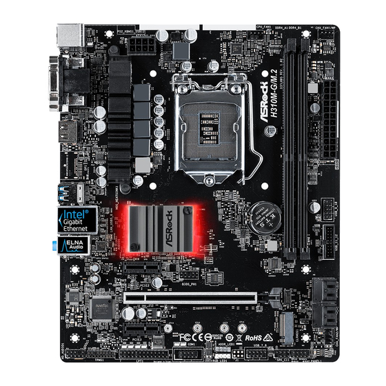
Page 11: Motherboard Layout
CHA_FAN1/WP ATX12V1 USB 3.1 Gen1 T: USB3 B: USB4 USB 2.0 CMOS Intel Top: T: USB5 RJ-45 Battery B: USB6 H310 PCIE1 BIOS H310M-G/M.2 PCIE2 AUDIO CODEC PCIE3 CLRMOS1 CHA_FAN2/WP RoHS PANEL1 ADDR_LED1 PLED PWRBTN COM1 LPT1 USB_7_8 TPMS1 SPK_CI1... - Page 12 H310M-G/M.2 No. Description ATX 12V Power Connector (ATX12V1) CPU Fan Connector (CPU_FAN1) 2 x 288-pin DDR4 DIMM Slots (DDR4_A1, DDR4_B1) Chassis/Water Pump Fan Connector (CHA_FAN1/WP) ATX Power Connector (ATXPWR1) USB 2.0 Header (USB_9_10) USB 3.1 Gen1 Header (USB_11_12) SATA3 Connector (SATA3_2)
-
Page 13: I/O Panel
1.4 I/O Panel No. Description No. Description USB 2.0 Ports (USB12) USB 2.0 Ports (USB5_6) D-Sub Port USB 3.1 Gen1 Ports (USB_3_4) LAN RJ-45 Port* HDMI Port Line In (Light Blue)** DVI-D Port Front Speaker (Lime)** PS/2 Keyboard/Mouse Port Microphone (Pink)** * here are two LEDs on each LAN port. - Page 14 H310M-G/M.2 ** To conigure 7.1 CH HD Audio, it is required to use an HD front panel audio module and enable the multi- channel audio feature through the audio driver. Please set Speaker Coniguration to “7.1 Speaker”in the Realtek HD Audio Manager.
-
Page 15: Chapter 2 Installation
Chapter 2 Installation his is a Micro ATX form factor motherboard. Before you install the motherboard, study the coniguration of your chassis to ensure that the motherboard its into it. Pre-installation Precautions Take note of the following precautions before you install motherboard components or change any motherboard settings. -
Page 16: Installing The Cpu
H310M-G/M.2 2.1 Installing the CPU 1. Before you insert the 1151-Pin CPU into the socket, please check if the PnP cap is on the socket, if the CPU surface is unclean, or if there are any bent pins in the socket. Do not force to insert the CPU into the socket if above situation is found. - Page 18 H310M-G/M.2 Please save and replace the cover if the processor is removed. he cover must be placed if you wish to return the motherboard for ater service.
-
Page 19: Installing The Cpu Fan And Heatsink
2.2 Installing the CPU Fan and Heatsink... -
Page 20: Installing Memory Modules (Dimm)
H310M-G/M.2 2.3 Installing Memory Modules (DIMM) his motherboard provides two 288-pin DDR4 (Double Data Rate 4) DIMM slots, and supports Dual Channel Memory Technology. 1. For dual channel coniguration, you always need to install identical (the same brand, speed, size and chip-type) DDR4 DIMM pairs. -
Page 22: Expansion Slots (Pci Express Slots)
H310M-G/M.2 2.4 Expansion Slots (PCI Express Slots) here are 3 PCI Express slots on the motherboard. Before installing an expansion card, please make sure that the power supply is switched of or the power cord is unplugged. Please read the documentation of the expansion card and make necessary hardware settings for the card before you start the installation. -
Page 23: Jumpers Setup
2.5 Jumpers Setup he illustration shows how jumpers are setup. When the jumper cap is placed on the pins, the jumper is “Short”. If no jumper cap is placed on the pins, the jumper is “Open”. Clear CMOS Jumper Short: Clear CMOS (CLRCMOS1) Open: Default 2-pin Jumper... -
Page 24: Onboard Headers And Connectors
H310M-G/M.2 2.6 Onboard Headers and Connectors Onboard headers and connectors are NOT jumpers. Do NOT place jumper caps over these headers and connectors. Placing jumper caps over the headers and connectors will cause permanent damage to the motherboard. System Panel Header... - Page 25 Chassis Intrusion and Please connect the SPEAKER DUMMY Speaker Header chassis intrusion and the DUMMY (7-pin SPK_CI1) chassis speaker to this (see p.6, No. 15) header. SIGNAL DUMMY Serial ATA3 Connectors hese four SATA3 (SATA3_0: connectors support SATA see p.6, No. 11) data cables for internal (SATA3_1: storage devices with up to...
- Page 26 H310M-G/M.2 Front Panel Audio Header his header is for PRESENCE# MIC_RET (9-pin HD_AUDIO1) OUT_RET connecting audio devices (see p.6, No. 22) to the front audio panel. OUT2_L J_SENSE OUT2_R MIC2_R MIC2_L 1. High Deinition Audio supports Jack Sensing, but the panel wire on the chassis must support HDA to function correctly.
- Page 27 ATX Power Connector his motherboard (24-pin ATXPWR1) provides a 24-pin ATX (see p.6, No. 5) power connector. To use a 20-pin ATX power supply, please plug it along Pin 1 and Pin 13. ATX 12V Power his motherboard Connector provides an 8-pin ATX (8-pin ATX12V1) 12V power connector.
- Page 28 H310M-G/M.2 RGB LED Header his header is used to connect (4-pin RGB_LED1) 12V G R RGB LED extension cable which (see p.6, No. 18) allows users to choose from various LED lighting efects. Caution: Never install the RGB LED cable in the wrong orienta- tion;...
- Page 29 2.7 M.2_SSD (NGFF) Module Installation Guide The M.2, also known as the Next Generation Form Factor (NGFF), is a small size and versatile card edge connector that aims to replace mPCIe and mSATA. he M.2 Socket (M2_1) supports SATA3 6.0 Gb/s module and M.2 PCI Express module up to Gen2 x4 (20 Gb/s).
- Page 30 H310M-G/M.2 Step 3 Move the standof based on the module type and length. he standof is placed at the nut location D by default. Skip Step 3 and 4 and go straight to Step 5 if you are going to use the default nut.
- Page 31 TS256GMTS400 Transcend SATA3 TS512GMTS600 Transcend SATA3 TS512GMTS800 V-Color SATA3 VLM100-120G-2280B-RD V-Color SATA3 VLM100-240G-2280RGB V-Color SATA3 VSM100-240G-2280 V-Color SATA3 VLM100-240G-2280B-RD SATA3 WDS100T1B0B-00AS40 SATA3 WDS240G1G0B-00RC30 For the latest updates of M.2_SSD (NFGG) module support list, please visit our website for details: http://www.asrock.com...
-
Page 32: Chapter 3 Software And Utilities Operation
H310M-G/M.2 Chapter 3 Software and Utilities Operation 3.1 Installing Drivers he Support CD that comes with the motherboard contains necessary drivers and useful utilities that enhance the motherboard’s features. Running The Support CD To begin using the support CD, insert the CD into your CD-ROM drive. he CD automatically displays the Main Menu if “AUTORUN”... -
Page 33: A-Tuning
3.2 A-Tuning A-Tuning is ASRock’s multi purpose sotware suite with a new interface, more new features and improved utilities. 3.2.1 Installing A-Tuning A-Tuning can be downloaded from ASRock Live Update & APP Shop. Ater the installation, you will ind the icon “A-Tuning“ on your desktop. Double-click the “A-Tuning“... - Page 34 H310M-G/M.2 System Info View information about the system. *he System Browser tab may not appear for certain models. FAN-Tastic Tuning Conigure up to ive diferent fan speeds using the graph. he fans will automatically shit to the next speed level when the assigned temperature is met.
- Page 35 Settings Conigure ASRock A-Tuning. Click to select "Auto run at Windows Startup" if you want A-Tuning to be launched when you start up the Windows operating system.
-
Page 36: Asrock Live Update & App Shop
Double-click on your desktop to access ASRock Live Update & APP Shop utility. *You need to be connected to the Internet to download apps from the ASRock Live Update & APP Shop. 3.3.1 UI Overview Category Panel Hot News... -
Page 37: Apps
3.3.2 Apps When the "Apps" tab is selected, you will see all the available apps on screen for you to download. Installing an App Step 1 Find the app you want to install. he most recommended app appears on the let side of the screen. he other various apps are shown on the right. - Page 38 H310M-G/M.2 Step 3 If you want to install the app, click on the red icon to start downloading. Step 4 When installation completes, you can ind the green "Installed" icon appears on the upper right corner. To uninstall it, simply click on the trash can icon...
- Page 39 Upgrading an App You can only upgrade the apps you have already installed. When there is an available new version for your app, you will ind the mark of "New Version" appears below the installed app icon. Step 1 Click on the app icon to see more details. Step 2 Click on the yellow icon to start upgrading.
-
Page 40: Bios & Drivers
H310M-G/M.2 3.3.3 BIOS & Drivers Installing BIOS or Drivers When the "BIOS & Drivers" tab is selected, you will see a list of recommended or critical updates for the BIOS or drivers. Please update them all soon. Step 1 Please check the item information before update. Click on to see more details. -
Page 41: Setting
3.3.4 Setting In the "Setting" page, you can change the language, select the server location, and determine if you want to automatically run the ASRock Live Update & APP Shop on Windows startup. -
Page 42: Asrock Rgb Led
H310M-G/M.2 3.4 ASRock RGB LED ASRock RGB LED is a lighting control utility speciically designed for unique individuals with sophisticated tastes to build their own stylish colorful lighting system. Simply by connecting the LED strip, you can customize various lighting schemes and patterns, including Static, Breathing, Strobe, Cycling, Music, Wave and more. - Page 43 ADDR_LED1 DO_ADDR VOUT H310M-G/M.2 1. Never install the RGB LED cable in the wrong orientation; otherwise, the cable may be damaged. 2. Before installing or removing your RGB LED cable, please power of your system and unplug the power cord from the power supply. Failure to do so may cause damages to motherboard components.
- Page 44 ASRock RGB LED Utility Now you can adjust the RGB LED color through the ASRock RGB LED utility. Download this utility from the ASRock Live Update & APP Shop and start coloring your PC style your way! Drag the tab to customize your preference.
-
Page 45: Chapter 4 Uefi Setup Utility
Chapter 4 UEFI SETUP UTILITY 4.1 Introduction his section explains how to use the UEFI SETUP UTILITY to conigure your system. You may run the UEFI SETUP UTILITY by pressing <F2> or <Del> right ater you power on the computer, otherwise, the Power-On-Self-Test (POST) will continue with its test routines. -
Page 46: Ez Mode
H310M-G/M.2 4.2 EZ Mode he EZ Mode screen appears when you enter the BIOS setup program by default. EZ mode is a dashboard which contains multiple readings of the system’s current status. You can check the most crucial information of your system, such as CPU speed, DRAM frequency, SATA information, fan speed, etc. -
Page 47: Advanced Mode
4.3 Advanced Mode he Advanced Mode provides more options to conigure the BIOS settings. Refer to the following sections for the detailed conigurations. To access the EZ Mode, press <F6> or click the "EZ Mode" button at the upper right corner of the screen. -
Page 48: Navigation Keys
H310M-G/M.2 4.3.2 Navigation Keys Use < > key or < > key to choose among the selections on the menu bar, and use < > key or < > key to move the cursor up or down to select items, then press <Enter>... -
Page 49: Main Screen
4.4 Main Screen When you enter the UEFI SETUP UTILITY, the Main screen will appear and display the system overview. My Favorite Display your collection of BIOS items. Press F5 to add/remove your favorite items. -
Page 50: Oc Tweaker Screen
H310M-G/M.2 4.5 OC Tweaker Screen In the OC Tweaker screen, you can set up overclocking features. Because the UEFI sotware is constantly being updated, the following UEFI setup screens and descriptions are for reference purpose only, and they may not exactly match what you see on your screen. - Page 51 Intel Turbo Boost Technology Intel Turbo Boost Technology enables the processor to run above its base operating frequency when the operating system requests the highest performance state. Intel Speed Shift Technology Enable/Disable Intel Speed Shit Technology support. Enabling will expose the CPPC v2 interface to allow for hardware controlled P-sates.
- Page 52 DRAM Clock Choose a frequency to override to clock delay for memory training. DRAM Clock controls memory training only if ASRock Timing Optimization is disabled. Primary Timing CAS# Latency (tCL) he time between sending a column address to the memory and the beginning of the data in response.
- Page 53 RAS to RAS Delay (tRRD_L) he number of clocks between two rows activated in diferent banks of the same rank. RAS to RAS Delay (tRRD_S) he number of clocks between two rows activated in diferent banks of the same rank. Write to Read Delay (tWTR_L) he number of clocks between the last valid write operation and the next read command to the same internal bank.
- Page 54 H310M-G/M.2 tRDRD_dg Conigure between module read to read delay. tRDRD_dr Conigure between module read to read delay. tRDRD_dd Conigure between module read to read delay. tRDWR_sg Conigure between module read to write delay. tRDWR_dg Conigure between module read to write delay.
- Page 55 tWRWR_dd Conigure between module write to write delay. Round Trip Timing RTL Init Value Conigure round trip latency init value for round trip latency training. IO-L Init Value Conigure IO latency init value for IO latency training. RTL (CH A) Conigure round trip latency for channel A.
- Page 56 H310M-G/M.2 ODT NOM (A1) Use this to change ODT (CH A) Auto/Manual settings. he default is [Auto]. ODT NOM (B1) Use this to change ODT (CH B) Auto/Manual settings. he default is [Auto]. ODT PARK (A1) Conigure the memory on die termination resistors' PARK for channel A.
- Page 57 Conigure the tCWL for Memory MRS MR2. MRS tCCD_L Conigure the tCL for Memory MRS MR6. Advanced Setting ASRock Timing Optimization Conigure the fast path through the MRC. Realtime Memory Timing Conigure the realtime memory timings. [Enabled] he system will allow performing realtime memory timing changes ater MRC_DONE.
- Page 58 H310M-G/M.2 MRC Fast Boot Enable Memory Fast Boot to skip DRAM memory training for booting faster. Voltage Coniguration CPU Vcore Voltage Use this to conigure CPU Vcore Voltage. he default value is [Auto]. GT Voltage Use this to conigure GT Voltage. he default value is [Auto].
-
Page 59: Advanced Screen
4.6 Advanced Screen In this section, you may set the conigurations for the following items: CPU Coniguration, Chipset Coniguration, Storage Coniguration, Super IO Conigura- tion, ACPI Coniguration, USB Coniguration and Trusted Computing. Setting wrong values in this section may cause the system to malfunction. UEFI Coniguration UEFI Setup Style Select the default mode when entering the UEFI setup utility. -
Page 60: Cpu Coniguration
H310M-G/M.2 4.6.1 CPU Coniguration Intel Hyper Threading Technology Intel Hyper hreading Technology allows multiple threads to run on each core, so that the overall performance on threaded sotware is improved. Active Processor Cores Select the number of cores to enable in each processor package. - Page 61 CFG Lock his item allows you to disable or enable the CFG Lock. CPU Thermal Throttling Enable CPU internal thermal control mechanisms to keep the CPU from overheat- ing. Intel Virtualization Technology Intel Virtualization Technology allows a platform to run multiple operating systems and applications in independent partitions, so that one computer system can function as multiple virtual systems.
-
Page 62: Chipset Coniguration
H310M-G/M.2 4.6.2 Chipset Coniguration Primary Graphics Adapter Select a primary VGA. Above 4G Decoding Enable or disable 64bit capable Devices to be decoded in Above 4G Address Space (only if the system supports 64 bit PCI decoding). VT-d Intel® Virtualization Technology for Directed I/O helps your virtual machine... - Page 63 PCIE ASPM Support his option enables/disables the ASPM support for all CPU downstream devices. PCH PCIE ASPM Support his option enables/disables the ASPM support for all PCH PCIE devices. DMI ASPM Support his option enables/disables the control of ASPM on CPU side of the DMI Link. PCH DMI ASPM Support his option enables/disables the ASPM support for all PCH DMI devices.
-
Page 64: Storage Coniguration
H310M-G/M.2 4.6.3 Storage Coniguration SATA Controller(s) Enable/disable the SATA controllers. SATA Aggressive Link Power Management SATA Aggressive Link Power Management allows SATA devices to enter a low power state during periods of inactivity to save power. It is only supported by AHCI mode. -
Page 65: Super Io Coniguration
4.6.4 Super IO Coniguration Serial Port Enable or disable the Serial port. Serial Port Address Select the address of the Serial port. Parallel Port Enable or disable the Parallel port. Change Settings Select the address of the Parallel port. Device Mode Select the device mode according to your connected device. -
Page 66: Acpi Coniguration
H310M-G/M.2 4.6.5 ACPI Coniguration Suspend to RAM Select disable for ACPI suspend type S1. It is recommended to select auto for ACPI S3 power saving. PS/2 Keyboard Power On Allow the system to be waked up by a PS/2 Keyboard. - Page 67 USB Mouse Power On Allow the system to be waked up by an USB mouse.
-
Page 68: Usb Coniguration
H310M-G/M.2 4.6.6 USB Coniguration Legacy USB Support Enable or disable Legacy OS Support for USB 2.0 devices. If you encounter USB compatibility issues it is recommended to disable legacy USB support. Select UEFI Setup Only to support USB devices under the UEFI setup and Windows/Linux operating systems only. -
Page 69: Trusted Computing
4.6.7 Trusted Computing Security Device Support Enable or disable BIOS support for security device. -
Page 70: Tools
H310M-G/M.2 4.7 Tools UEFI Tech Service Contact ASRock Tech Service if you are having trouble with your PC. Please setup network coniguration before using UEFI Tech Service. Instant Flash Save UEFI iles in your USB storage device and run Instant Flash to update your UEFI. - Page 71 Network Coniguration Use this to conigure internet connection settings for Internet Flash. Internet Setting Enable or disable sound efects in the setup utility. UEFI Download Server Select a server to download the UEFI irmware.
-
Page 72: Hardware Health Event Monitoring Screen
H310M-G/M.2 4.8 Hardware Health Event Monitoring Screen his section allows you to monitor the status of the hardware on your system, including the parameters of the CPU temperature, motherboard temperature, fan speed and voltage. Fan Tuning Measure Fan Min Duty Cycle. - Page 73 CHA_FAN2 Control Mode Select PWM mode or DC mode for CHA_FAN2. Chassis Fan 1 Setting Select a fan mode for Chassis Fan 1, or choose Customize to set 5 CPU temperatures and assign a respective fan speed for each temperature. Chassis Fan 1 Temp Source Select a fan temperature source for Chassis Fan 1.
-
Page 74: Security Screen
H310M-G/M.2 4.9 Security Screen In this section you may set or change the supervisor/user password for the system. You may also clear the user password. Supervisor Password Set or change the password for the administrator account. Only the administrator has authority to change the settings in the UEFI Setup Utility. Leave it blank and press enter to remove the password. -
Page 75: Boot Screen
4.10 Boot Screen his section displays the available devices on your system for you to conigure the boot settings and the boot priority. Fast Boot Fast Boot minimizes your computer's boot time. In fast mode you may not boot from an USB storage device. he VBIOS must support UEFI GOP if you are using an external graphics card. - Page 76 H310M-G/M.2 Full Screen Logo Enable to display the boot logo or disable to show normal POST messages. AddOn ROM Display Enable AddOn ROM Display to see the AddOn ROM messages or conigure the AddOn ROM if you've enabled Full Screen Logo. Disable for faster boot speed.
- Page 77 Launch Storage OpROM Policy Select UEFI only to run those that support UEFI option ROM only. Select Legacy only to run those that support legacy option ROM only. Select Do not launch to not execute both legacy and UEFI option ROM. Other PCI Device ROM Priority For PCI devices other than Network.
-
Page 78: Exit Screen
H310M-G/M.2 4.11 Exit Screen Save Changes and Exit When you select this option the following message, “Save coniguration changes and exit setup?” will pop out. Select [OK] to save changes and exit the UEFI SETUP UTILITY. Discard Changes and Exit When you select this option the following message, “Discard changes and exit... - Page 79 Contact Information If you need to contact ASRock or want to know more about ASRock, you’re welcome to visit ASRock’s website at http://www.asrock.com; or you may contact your dealer for further information. For technical questions, please submit a support request form at https://event.asrock.com/tsd.asp...
- Page 80 DECLARATION OF CONFORMITY Per FCC Part 2 Section 2.1077(a) ASRock Incorporation Responsible Party Name: Address: 13848 Magnolia Ave, Chino, CA91710 Phone/Fax No: +1-909-590-8308/+1-909-590-1026 hereby declares that the product Product Name : Motherboard H310M-G/M.2 Model Number : Conforms to the following speci cations:...
- Page 81 EU Declaration of Conformity For the following equipment: Motherboard (Product Name) H310M-G/M.2 / ASRock (Model Designation / Trade Name) ASRock Incorporation (Manufacturer Name) 2F., No.37, Sec. 2, Jhongyang S. Rd., Beitou District, Taipei City 112, Taiwan (R.O.C.) (Manufacturer Address) EMC —Directive 2014/30/EU (from April 20th, 2016) ☐...
Need help?
Do you have a question about the H310M-G/M.2 and is the answer not in the manual?
Questions and answers