Table of Contents

Related Manuals for SECURECOM SC-GSM

Summary of Contents for SECURECOM SC-GSM
- Page 1 Analog phone line simulator (GSM gateway) or translation of Contact ID signals to SMS messages and alarm calls. One device with 2 independent operating modes. Manual v1.3 SC-GSM 1 EN Alarm Signaling Communicator v1.3...
-
Page 2: Table Of Contents
Setting the signaling in standalone mode ................ 10 4.7.2 The Contact ID codes comparation .................. 10 4.7.3 The reporting procedure ....................11 5 LED signals ............................12 6 Most frequently used Contact ID codes ....................12 SC-GSM 2 EN Alarm Signaling Communicator v1.3... -
Page 3: Short Functional Description Of Device
Power 9-30V (DC) Power consumption 300mA (max.) / 100mA (idle) Telephone line data Line voltage Loop current 25mA Load impedance 100-470 Ohm Dial tone 425Hz Operating temperature 0…+70°C Size 40x75x15mm SC-GSM 3 EN Alarm Signaling Communicator v1.3... -
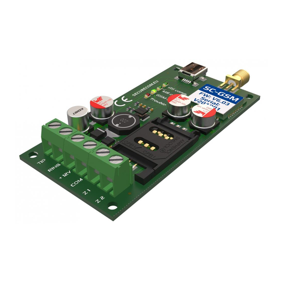
Page 4: Product Layout
Simulated landline for the alarm control panel’s TIP/RING input Line voltage: 48V, Loop current: 25mA, Impedance: 300ohm (TIP/RING) INPUTS (Z1, Z2) Contact Input (to negative supply “COM” ) for transmission of the signal of external switches SC-GSM 4 EN Alarm Signaling Communicator v1.3... -
Page 5: Connection
3.2 Emulated phone line The TIP and RING terminals of the SC-GSM device provides an emulated phone line. Connect these terminals where the PSTN (regular phone line) is supposed to be connected to the device that will use this communicator. In case of connecting to alarm panel, use the INCOMMING LINE terminals, (usually marked with TIP/RING or T/R, or Ti/Ri...). -
Page 6: Configuration Of Device
When connected to that machine for first time, the driver will be installed first, then the new drive will be found. This drive is the flash memory of SC-GSM device, and contains the software and this manual. You can run the software from device, or copy it to your PC and run it from there. -
Page 7: Moving Data Between The Pc And The Device
Sends the SMS messages belonging to the event CALL(1) Calls the first set number DTMF recd. got DTMF code, that is acknowledgement from the notified number Status of USB connection (Connected or Disconnected) SC-GSM 7 EN Alarm Signaling Communicator v1.3... -
Page 8: General Setting
The phone device (alarm panel) connected to the RING/TIP terminals make the dialing, the SC-GSM device just dials that number, and opens the VOICE channel to transfer all sounds in high quality through GSM network. In case of incoming call, the device will ringing, the connected phone device or alarm panel. -
Page 9: Standalone Mode
Chapter 6, or the “Contact-ID-codes-with-explanation.PDF” file. The best example of usage of these inputs is when the SC-GSM is used with alarm panel, to send a QUICK signal of an alarm state, while the dialer in alarm panel slowly makes the complete reporting of complete events through the emulated phone line. -
Page 10: Setting The Signaling In Standalone Mode
If the received Contact ID Code fits the setting in one line of the table, the SC-GSM will perform the procedure of calls and messages as set in that line. Each line is independent from another. You can use the same Code in several lines, if any of other “filters”... -
Page 11: The Reporting Procedure
If Part (partition) or Zone/User (zone/user) is left blank, that value in the Contact ID message will be disregarded, the SC-GSM will make the calls and sent the messages that are set in this line, no matter what value was sent by alarm panel (if the other fields fit the received message) -
Page 12: Led Signals
144 Sensor tamper 401 Arm/disarm by user 300 System Trouble 602 Periodic test report 301 AC Loss 626 Time/Date trouble 302 Low system battery 627 Installer programming 311 Battery Missing/Dead 316 System Tamper SC-GSM 12 EN Alarm Signaling Communicator v1.3...
Need help?
Do you have a question about the SC-GSM and is the answer not in the manual?
Questions and answers