
Related Manuals for SECURECOM SC-GSM

Summary of Contents for SECURECOM SC-GSM
-
Page 1: Table Of Contents
Universal GSM Gateway Security Monitoring Service Emulation Device Installing and programming Manual 2017-02-02 -for version 3.14 and later- Dcument revision: 5... -
Page 2: Table Of Contents
Moving data between the PC and the device ................6 Device code lock (protection) ..................... 6 Device Status ..........................7 General setting ........................... 7 Transparent mode ........................8 Standalone mode ........................9 LED signals ............................12 Most frequently used Contact ID codes ..................12 Copyright © 2016 - SECURECOM... -
Page 3: Short Functional Description Of Device
Technical specifications Power 9-30V (DC) • Power consumption 300mA (max.) / 100mA (idle) Telephone line data • Line voltage Loop current 25mA Load impedance 100-470 Ohm Dial tone 425Hz Operating temperature 0…+70°C • Size 40x75x15mm • Copyright © 2016 - SECURECOM... -
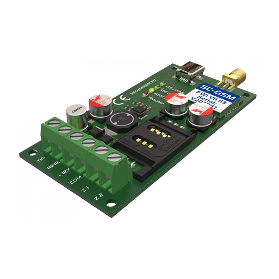
Page 4: Product Layout
SIM card. Please be sure that the SIM card is placed properly before powering up the device. Warning: The SIM card should never be removed or added while the device is powered up. Copyright © 2016 - SECURECOM... -
Page 5: Power
This drive is the flash memory of Securecom device, and contains the software and this manual. You can run the software from device, or copy it to your PC and run it from there. When the device is powered through terminals, the USB cable can be plugged or unplugged at any time, it will not affect the device. -
Page 6: Moving Data Between The Pc And The Device
After closing re-starting the software, the code entry box is displayed again. Only after the right code was entered, the software will be fully functional, presenting the whole window with all settings displayed and editable. Copyright © 2016 - SECURECOM... -
Page 7: Device Status
3 times. If the Acknowledge is received, all further calls for that event are terminated. This means that the called party who acknowledges the call will STOP the calls to numbers that are next in order (T1/T4) Copyright © 2016 - SECURECOM... -
Page 8: Transparent Mode
Contact ID code in the Chapter 6, or the “Contact-ID-codes-with- explanation.PDF” file. The best example of usage of these inputs is when the securecom is used with alarm panel, to send a QUICK signal of an alarm state, while the dialer in alarm panel slowly makes the complete reporting of complete events through the emulated phone line. -
Page 9: Standalone Mode
Another example: When the alarm occurs in zone 2 of the alarm system, the code 8556 18 1 130 01 002 will be transmitted, and the Securecom device will call the phone numbers T1 ( 01234567891) and expect the ACKNOWLEDGE from the called party (any button on dialer pressed) will be expected. - Page 10 SMS sending If the received Contact ID Code fits the setting in one line of the table, the Securecom will perform the procedure of calls and messages as set in that line. Each line is independent from another. You can use the same Code in several lines, if any of other “filters”...
- Page 11 If Part (partition) or Zone/User (zone/user) is left blank, that value in the Contact • ID message will be disregarded, the securecom will make the calls and sent the messages that are set in this line, no matter what value was sent by alarm panel (if the other fields fit the received message) Copyright ©...
-
Page 12: Led Signals
626 Time/Date trouble 144 Sensor tamper 627 Installer programming 300 System Trouble 301 AC Loss 302 Low system battery 311 Battery Missing/Dead 316 System Tamper 321 Bell 1 383 Sensor tamper 401 Arm/disarm by user Copyright © 2016 - SECURECOM...
Need help?
Do you have a question about the SC-GSM and is the answer not in the manual?
Questions and answers