Table of Contents
Advertisement
Advertisement
Chapters
Table of Contents

Related Manuals for Honda CB1000RA


Summary of Contents for Honda CB1000RA
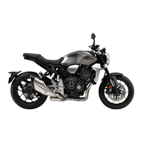
- Page 1 CB1000RA OWNER’S MANUAL...
- Page 2 This publication includes the latest production information available before printing. Honda Motor Co., Ltd. reserves the right to make changes at any time without notice and without incurring any obligation.
- Page 3 Congratulations on your purchase of a new The following codes in this manual ● Honda vehicle. Your selection of a Honda indicate each country. makes you part of a worldwide family of The illustrations here in are based on the ●...
- Page 4 A Few Words About Safety DANGER Your safety, and the safety of others, is very important. Operating this vehicle safely is an You WILL be KILLED or SERIOUSLY important responsibility. HURT if you don’t follow instructions. To help you make informed decisions about safety, we have provided operating WARNING procedures and other information on safety...
-
Page 5: Table Of Contents
Contents Vehicle Safety P. 2 Operation Guide P. 18 Maintenance P. 97 Troubleshooting P. 141 Information P. 155 Specifications P. 176 Index P. 179... -
Page 6: Vehicle Safety
Vehicle Safety This section contains important information for safe riding of your vehicle. Please read this section carefully. Safety Guidelines ..........P. 3 Image Labels............P. 6 Safety Precautions..........P. 11 Riding Precautions ..........P. 12 Accessories & Modifications......P. 16 Loading .............. -
Page 7: Safety Guidelines
Safety Guidelines Safety Guidelines Before Riding Make sure that you are physically fit, mentally Follow these guidelines to enhance your safety: focused and free of alcohol and drugs. Check Perform all routine and regular inspections ● that you and your passenger are both wearing specified in this manual. - Page 8 Safety Guidelines Make Yourself Easy to See Keep Your Honda in Safe Condition Make yourself more visible, especially at night, It's important to keep your vehicle properly by wearing bright reflective clothing, positioning maintained and in safe riding condition. yourself so other drivers can see you, signaling...
- Page 9 Safety Guidelines If you decide to continue riding, first turn the Never run your vehicle inside a garage or other ignition switch to the (Off) position, and enclosure. evaluate the condition of your vehicle. Inspect WARNING for fluid leaks, check the tightness of critical nuts Running the engine of your vehicle and bolts, and check the handlebar, control levers, brakes, and wheels.
-
Page 10: Image Labels
Image Labels Image Labels The following pages describe the label Read instructions contained in Owner's meanings. Some labels warn you of Manual carefully. potential hazards that could cause serious injury. Others provide important safety information. Read this information carefully Read instructions contained in Shop Manual and don't remove the labels. - Page 11 Image Labels Except KO, III KO type BATTERY LABEL DANGER • Keep flame and spark away from the battery. Battery produce explosive gas that can cause explosion. • Wear the eye protection and rubber gloves when handling the battery, or you can get burned or lose your eyesight by the battery electrolyte.
- Page 12 Image Labels RADIATOR CAP LABEL DANGER Except KO, III KO type NEVER OPEN WHEN HOT. Hot coolant will scald you. Relief pressure valve begins to open at 1.1 kgf/cm ACCESSORIES AND LOADING WARNING LABEL WARNING ED, Ⅱ ED type ACCESSORIES AND LOADING •...
- Page 13 Image Labels REAR CUSHION LABEL Except KO, III KO type GAS FILLED Do not open. Do not heat. TYRE INFORMATION & DRIVE CHAIN LABEL Except KO, III KO type Cold tyre pressure: [Driver only] Front 250 kPa (2.50 kgf/cm , 36 psi) Rear 290 kPa (2.90 kgf/cm , 42 psi)
- Page 14 Image Labels SAFETY REMINDER LABEL Except KO, III KO type For your protection, always wear helmet, protective apparel. FUEL LABEL Except KO, III KO type Unleaded petrol only ETHANOL up to 10 % by volume...
-
Page 15: Safety Precautions
Safety Precautions Safety Precautions Face shield with unobstructed field of vision ● or other approved eye protection Ride cautiously and keep your hands on the ● WARNING handlebar and feet on the footpegs. Not wearing a helmet increases the Keep passenger's hands onto the seat strap ●... -
Page 16: Riding Precautions
Riding Precautions Riding Precautions Exercise caution on low traction surfaces. ● The tyres slip more easily on such surfaces and braking distances are Running-in Period longer. During the first 500 km (300 miles) of running, Avoid continuous braking. ● follow these guidelines to ensure your vehicle's Repeated braking, such as when future reliability and performance. - Page 17 Riding Precautions Anti-lock Brake System (ABS) Engine Braking This model is equipped with an Anti-lock Brake Engine braking helps slow your vehicle down System (ABS) designed to help prevent the when you release the throttle. For further brakes from locking up during hard braking. slowing action, downshift to a lower gear.
- Page 18 Riding Precautions Slowly lean the vehicle to the left until its Parking weight rests on the side stand. Park on a firm, level surface. ● Turn the handlebar fully to the left. If you must park on a slight incline or loose ●...
- Page 19 Torque Control may not compensate for rough Honda selectable torque control road conditions or rapid throttle operation. When the Honda selectable torque control Always consider road and weather conditions, (Torque Control) detects rear wheel spin during as well as your skills and condition, when acceleration, the system will limit the amount of applying throttle.
-
Page 20: Accessories & Modifications
We strongly advise that you do not add any seriously hurt or killed. accessories that were not specifically designed for your vehicle by Honda or make Follow all instructions in this owner's modifications to your vehicle from its original manual regarding accessories and design. -
Page 21: Loading
Loading Loading WARNING Carrying extra weight affects your vehicle's ● Overloading or improper loading can handling, braking and stability. cause a crash and you can be seriously Always ride at a safe speed for the load you hurt or killed. are carrying. - Page 22 Parts Location Tool kit (P.95) Document bag (P.96) Main fuse/ABS fuse (P.153) Fuse box (P.153) Battery (P.117) Front brake fluid reservoir (P.125) Front suspension spring preload adjuster (P.136) Front brake lever (P.135) Rear brake fluid reservoir (P.125) Engine oil level inspection window (P.121) Engine oil fill cap...
- Page 23 Front suspension rebound damping/compression damping adjuster (P.137) (P.138) Fuel fill cap (P.92) Throttle grip (P.134) Front seat (P.118) Rear seat (P.119) Clutch lever (P.131) Coolant reserve tank (P.123) Rear suspension spring preload adjuster (P.139) Drive chain (P.129) Side stand (P.128) Shift lever (P.88)
- Page 24 Instruments You can change the speed and mileage, and fuel mileage meter units. (P.42) (P.58) Do not operate the display functions for a long time with the engine stopped. It may result in a low (or dead) battery.
- Page 25 (P.23) Status bar Indicator area (P.25) (P.27) RIDING MODE (P.80) RIDING MODE PARAMETER (P.80) Honda Smartphone Voice Control system area (P.77) Gear position indicator (P.26) Quick Shifter indicator INFO area (P.28) II ED, II GS, III KO type Pop-up information (P.67)
- Page 26 Instruments (Continued) Basic Operations You can operate and set the various functions of the display using the switches on the left handlebar. Function switch Sel switch When switching or setting the display, refer to the switch operation guide is displayed. Type of the switch operation guide: : Press on the sel switch...
- Page 27 Speedometer/Tachometer/Fuel gauge/Side stand indicator area Display type: TYPE 1 Side stand indicator Tachometer red zone Comes on when the side stand is down. (excessive engine rpm range) Fuel gauge Remaining fuel when only 1st (E) segment starts flashing: approximately 3.5 L (0.92 US gal, 0.77 Imp gal) At the same time, the reserve fuel indicator is comes on.
- Page 28 Instruments (Continued) Speedometer/Tachometer/Fuel gauge/Side stand indicator area has four display types. The display and arrangement of speedometer, tachometer and fuel gauge change depending on each display type. To change the display type: (P.42) (P.52) Display type: TYPE 4 Display type: TYPE 2 Display type: TYPE 3 Tachometer Side stand indicator...
- Page 29 Status bar Status icon Displays the status of the Honda Clock (12-hour or 24-hour display) Smartphone Voice Control To set the clock: (P.42) (P.57) system. (P.77) Coolant temperature gauge Displays the coolant temperature. Even if the engine coolant temperature is Display range: 35°C to 132°C...
- Page 30 Instruments (Continued) Gear position indicator The gear position is shown in the gear position indicator. “-” appears when the transmission is not shifted properly. Quick Shifter indicator II ED, II GS, III KO type Displays the current status of the Quick Shifter. This indicator is displayed in the gear position indicator.
- Page 31 Indicator area High beam indicator High coolant temperature indicator If it comes on while riding: (P.143) Low oil pressure indicator Comes on when the electrical system is turned on. Goes off when the engine starts. If it comes on while engine is running: (P.144) Low fuel indicator Comes on when there is only reserve fuel...
- Page 32 Instruments (Continued) INFO area To switch page of the INFO area The INFO area displays various vehicle To change page of the INFO area, push the information. sel switch in the direction of INFO page 1 The INFO area has four pages and displays four pieces of information on each page.
- Page 33 The types of information item that can be VOLTAGE (P.36) displayed in the INFO area are as follows: DATE (P.36) TOTAL (P.30) User letter (P.36) TRIP A (P.30) Logo (P.36) TRIP A CONS. (P.31) SHIFT POINT (P.37) TRIP A AVG. CONS. (P.31) FUEL CONS.
- Page 34 Instruments (Continued) Odometer [TOTAL] Tripmeter A [TRIP A] Total distance ridden. Distance ridden since the tripmeter A was reset. When “------” is displayed, go to your dealer for service. When “----.-” is displayed, go to your dealer for service. To reset the tripmeter A: (P.41)
- Page 35 Tripmeter A fuel consumption [TRIP A Tripmeter A average fuel mileage CONS.] [TRIP A AVG. CONS.] Displays the tripmeter A fuel consumption Displays the average fuel mileage since the tripmeter A was reset. since the tripmeter A was reset. The average fuel mileage will be calculated Display range: based on the value on tripmeter A.
- Page 36 Instruments (Continued) Tripmeter B [TRIP B] Tripmeter B fuel consumption [TRIP B CONS.] Distance ridden since the tripmeter B was reset. Displays the tripmeter B fuel consumption since the tripmeter B was reset. Display range: : 0.0 to 299.9 L (GAL) ED, II ED, U : 0.0 to 299.9 L GS, II GS, KO, III KO...
- Page 37 Tripmeter B average fuel mileage [TRIP B Current fuel mileage [INST. CONS.] AVG. CONS.] Displays the current instant fuel mileage. Displays the average fuel mileage since the Display range: tripmeter B was reset. : 0.0 to 299.9 L/100 km (km/L, ED, II ED, U The average fuel mileage will be calculated based mile/GAL or mile/L)
- Page 38 Instruments (Continued) Average fuel mileage [AVG. CONS.] Average speed [AVG. SPEED] Displays the average fuel mileage since the Displays the average speed since the average average fuel mileage was reset. speed was reset. Display range: Display range: : 0.0 to 299.9 L/100 km (km/L, : 0 to 299 km/h (0 to 186 mph) ED, II ED, U ED, II ED, U...
- Page 39 Elapsed time [ELAPSED] Numerical tachometer display [REV] Displays the engine operating time since the Displays the engine revolutions per minutes. elapsed time was reset. Display range: 00:00 to 99:59 (hours:minutes) Above 99:59: back to 00:00 ● Throttle grip angle [GRIP ANGLE] Displays the throttle grip angle during operation.
- Page 40 Instruments (Continued) Battery voltage [VOLTAGE] User letter Displays the current voltage. Displays the characters of user's choice. To set the USER LETTER: (P.42) (P.56) Date [DATE] Displays the date of today. Logo Displays the CB1000R logo. To set the date: (P.42) (P.57)
- Page 41 SHIFT POINT set value [SHIFT POINT] Fuel consumption in this time [FUEL CONS. Displays the SHIFT POINT set value. Display range: 5,000 - 11,400 r/min Displays the fuel consumption since the electrical system was turned on. Display range: : 0.0 to 50.0 L (GAL) ED, II ED, U : 0.0 to 50.0 L GS, II GS, KO, III KO...
- Page 42 Instruments (Continued) Average fuel mileage in this time Average speed in this time [AVG. [AVG. CONS. SPEED Displays the average fuel mileage since the Displays the average speed since the electrical system was turned on. electrical system was turned on. Display range: Display range: : 0 to 299 km/h (0 to 186 mph)
- Page 43 Elapsed time in this time [ELAPSED Reserve tripmeter [RES TRIP] Distance ridden since the reserve fuel Displays the engine operating time since the indicator lights. electrical system was turned on. Display range: Display range: 00:00 to 99:59 (hours:minutes) : 0.0 to 9999.9 km (mile) ED, II ED, U Above 99:59: back to 00:00.
- Page 44 Instruments (Continued) Reserve fuel consumption [RES FUEL Blank display CONS.] Display the blank. Displays the fuel consumption since the reserve fuel indicator lights. Display range: : 0.0 to 299.9 L (GAL) ED, II ED, U : 0.0 to 299.9 L GS, II GS, KO, III KO When the reserve fuel indicator is off: ●...
- Page 45 Also, the tripmeter A, tripmeter A fuel To Reset the Information consumption and tripmeter A average fuel Select the page in the INFO area that mileage are automatically reset when only containing the item you want to reset with the reserve fuel remains in the fuel tank (the of the sel switch.
- Page 46 Instruments (Continued) Setting mode To shift to the setting mode Push and hold the sel switch in the direction of To select the desired setting menu, operate the sel switch on the left handlebar. When switching to setting mode, the clock, indicators and speed are displayed at the top of the screen.
- Page 47 Setting flow Ordinary display Setting mode RIDING MODE (P.47) QUICK SHIFTER (P.48) II ED, IIGS, III KO type SHIFT POINT (P.49) FUNCTION SELF-CANCELLING TURN (P.50) SIGNALS TRIP A AUTO RESET (P.50) HISS (P.51) DISPLAY Push/Press Push and hold/Press and hold Continued...
- Page 48 Instruments (Continued) FUNCTION DISPLAY TYPE (P.52) BRIGHTNESS (P.53) DISPLAY BACKGROUND (P.54) FAVORITE INFORMATION (P.55) USER LETTER (P.56) GENERAL Push/Press Push and hold/Press and hold...
- Page 49 DISPLAY DATE & TIME (P.57) UNIT (P.58) GENERAL LANGUAGE (P.59) RESTORE DEFAULT (P.60) BLUETOOTH PAIRING RESET (P.61) SERVICE Push/Press Push and hold/Press and hold Continued...
- Page 50 Instruments (Continued) GENERAL MAINTENANCE (P.62) EQUIPMENT SERVICE (P.65) QS INITIALIZE (P.65) (P.66) REGULATORY (P.66) Push/Press Push and hold/Press and hold...
-
Page 51: Operation Guide
RIDING MODE (P.80) To return to the initialize settings: You can change the setting value of the Push and hold the sel switch in the direction USER MODE. Reset the setting according to the switch Select the parameter ("P", "EB" or "T" ) using operation guide. - Page 52 Instruments (Continued) Select the "UP" or "DOWN" using the QUICK SHIFTER up or sel down switch. II ED, II GS, III KO type Select to the desired setting according to You can change the setting of the Quick the switch operation guide. (P.22) Shifter.
- Page 53 Select the "ON/OFF" or "SHIFT POINT" using SHIFT POINT of the sel switch. ON/OFF : You can activate or deactivate Select to the desired setting according to the shift up mode. the switch operation guide. (P.22) SHIFT POINT : You can change the engine Return to the ordinary display to complete revolutions at which the the setting.
- Page 54 Instruments (Continued) SELF-CANCELLING TURN SIGNALS TRIP A AUTO RESET You can enable or disable turn signal You can enable or disable the tripmeter A automatic cancellation. automatic reset mode. (P.74) (P.41) Select the "ON" or "OFF" using Select the "ON" or "OFF" using the sel switch.
- Page 55 HISS You can ON (blinks) or OFF (off) the HISS. Select the "ON" (blinks) or "OFF" (off) using of the sel switch. Return to the ordinary display to complete the setting. (P.42) To continue setting, push the sel switch in the direction of to return to the upper hierarchy.
- Page 56 Instruments (Continued) DISPLAY TYPE You can change the display type of speedometer / tachometer / fuel gauge. (P.23) Select the display type ("TYPE 1", "TYPE 2" "TYPE 3" or "TYPE 4") using of the sel switch. Return to the ordinary display to complete the setting.
- Page 57 BRIGHTNESS You can adjust the backlight brightness to one of the eight levels or select the auto adjustment. Automatic brightness control: (P.164) The display can become dark when the display is very hot. If it does not restore the original brightness, contact your dealer. Select the backlight brightness using of the sel switch.
- Page 58 Instruments (Continued) BACKGROUND You can change the setting of the background to one of the three colours or select the auto adjustment. Automatic Background Control: (P.164) Select the background colour using of the sel switch. Return to the ordinary display to complete the setting.
- Page 59 FAVORITE INFORMATION You can change the information items displayed in the INFO area. (P.28) Select the page of the INFO area ("INFO1", "INFO2", "INFO3" or "INFO4" using of the sel switch. Select to the desired setting according to the switch operation guide. (P.22) If you select the item that is already selected in another area, the previously...
- Page 60 Instruments (Continued) USER LETTER You can edit the USER LETTER with up to 10 characters. Edit the USER LETTER. To select the character using the sel switch. To set the character using the function switch. Select the "OK", and then press the function switch.
- Page 61 DATE & TIME Select the "24h or 12h", "YEAR", "MONTH - DAY", "HOUR - MINUTE" or "am / pm" using of the sel switch. Select the desired setting according to the switch operation guide. (P.22) When "24 / 12" is set to 24-hour indication, "am / pm"...
- Page 62 Instruments (Continued) UNIT You can change the speed and mileage, and fuel mileage meter units. Select the "SPEED" or "FUEL CONS." using of the sel switch. :"TEMP" is displayed but ED, II ED, U type not usable. :"SPEED" and GS, II GS, KO, III KO type "TEMP"...
- Page 63 LANGUAGE Changes the system language. Select the language using of the sel switch. Return to the ordinary display to complete the setting. (P.42) To continue setting, push the sel switch in the direction of to return to the upper hierarchy. The set value is retained.
- Page 64 Instruments (Continued) The following items are restored to their RESTORE DEFAULT default values: The set values can be returned to the default • DISPLAY TYPE settings. • SHIFT POINT Reset the settings according to the switch • BRIGHTNESS operation guide. •...
- Page 65 BLUETOOTH PAIRING RESET You can reset the pairing record of Bluetooth ® To connect the device (P.77) Reset the settings according to the switch operation guide. (P.22) If the pairing information remains in your smartphone even if the pairing information is deleted from the vehicle, the smartphone may be connected to the vehicle again.
- Page 66 Instruments (Continued) Display range: MAINTENANCE DISTANCE: You can check the next periodic inspection : -----, 12,000 to -99,999 km time and next engine oil change. ED, II ED, U (8,000 to -99,999 mile) You can change the setting of the next : -----, 12,000 to -99,999 km KO, III KO periodic inspection and next engine oil...
- Page 67 When reaching any of the following, the pop-up information is appears in the ordinary display. (P.67) “500 km” (“300 mile”) from the next ● periodic inspection. “100 km” (“60 mile”) from the next engine ● oil change. One month before the set month. ●...
- Page 68 Instruments (Continued) Next inspection setting Select the desired setting according to the Select “ ” (periodic inspection ) or “ ” switch operation guide. (engine oil change) using of the If you press and hold of the sel sel switch. switch while setting the “DISTANCE”, it will move every 1000.
- Page 69 EQUIPMENT QS INITIALIZE "EQUIPMENT" is displayed but not selectable. "QS INITIALIZE" is displayed but not selectable. Continued...
- Page 70 Instruments (Continued) REGULATORY Displays a current problem with the vehicle. Displays the radio wave authentication If your vehicle has problem, DTC index is screen. displayed. Reduce speed and have your vehicle inspected by your dealer as soon as possible. DTC indexes...
- Page 71 Pop-up information In the following cases, pop-up information is displayed at the INFO area. Maintenance information: ● When the inspection time of your vehicle is approaching. When your vehicle has multiple pieces of information, pop-up information display appears alternately. Maintenance Information Indication Explanation Remedy...
- Page 72 Instruments (Continued) Tachometer colour function Shift Up Mode When shift up mode is ON, the tachometer colour changes according to the shift point setting. To set the shift up mode (P.42) (P.49) The tachometer blinks yellow when the engine revolutions exceeds the set value of SHIFT POINT.
- Page 73 Indicators If one of these indicators does not come on when it should, have your dealer check for problems. Refer to the "Instruments" about indicators appeared on the display: (P.27) Left turn signal indicator Right turn signal indicator Neutral indicator Comes on when the transmission is in Neutral.
- Page 74 Indicators (Continued) Torque Control indicator Comes on when the electrical system is ● turned on. Goes off when your speed reaches approximately 5 km/h (3 mph) to indicate Torque Control is ready to work. Blinks when Torque Control is operating. ●...
- Page 76 Switches Engine stop switch/ Start button Left handlebar switch (P.74) Should normally remain in the (Run) position. In an emergency, switch to the (Stop) position to stop the engine.
- Page 77 Ignition Switch (On) Switches the electrical system on/off, locks Turns electrical system the steering. on for starting/riding. Key can be removed when in the (Off) or (Off) (Lock) position. Turns engine off. (Lock) Locks steering. Continued...
- Page 78 Switches (Continued) Left handlebar switches Headlight dimmer/Passing light control switch • : High beam • : Low beam • : Flashes the high beam headlight. switch MODE Used to change the riding mode. (P.80) Horn button Turn signal switch The turn signal will automatically stop when you complete the turn. (You can manually cancel the lights by pressing the switch in.) When used for a lane change, the turn signal will automatically stop in about 7 seconds or after riding 150 m (164 yards).
- Page 79 (P.22) Also used to set the riding mode and to (P.80) operate the Honda Smartphone Voice Control system (P.77) Hazard switch Switchable when the electrical system is on. Can be turned to off regardless of whether the electrical system is on or off.
- Page 80 Switches (Continued) Steering Lock Locking Turn the handlebar all the way to the left. Lock the steering when parking to help Push the key down, and turn the ignition prevent theft. switch to the (Lock) position. A U-shaped wheel lock or similar device is Jiggle the handlebar if the lock is difficult also recommended.
- Page 81 ® see the following URL: registered trademarks owned by Bluetooth https://global.honda/voice-control-system/ SIG, Inc., and any use of such marks by Honda Motors Co., Ltd., is under license. Other trademarks and trade names are those of their respective owners. Continued...
- Page 82 Honda Smartphone Voice Control system (Continued) The system itself has certain limitations. Costs of network communication and ● Therefore, you must verify the voice communication equipment necessary for guidance and information in the meter the use of this feature shall be borne by provided by the system by carefully the user himself/herself.
- Page 83 Reset the pairing information according to the Voice Control system functionality and services. switch operation guide. (P.22) After resetting, complete pairing while the Honda cannot and does not provide any Bluetooth indicator flashing by operated the ® warranty or guarantee of future Honda application on your smartphone.
- Page 84 Riding mode You can change the riding mode. Current riding mode P level The riding mode consists of the following (Engine power parameters. output level) P: Engine output level T: Torque control level EB: Engine brake level EB level (Engine brake level) T level (Torque control level)
- Page 85 Riding mode has four modes. [USER] Available riding modes: [STANDARD], [RAIN], Each initial setting level can be changed. [USER] and [SPORT] [STANDARD] : Standard, all-round mode for a variety of situations. [RAIN] : Good for stable riding on slippery surfaces such as rainy conditions. [SPORT] : This mode is suitable for sports riding.
- Page 86 Riding mode (Continued) P level (Engine power output level) EB level (Engine brake level) P level has three setting levels. EB level has three setting levels. Available setting range: 1 to 3 Available setting range: 1 to 3 Level 1 has the least power. Level 1 has the weakest engine braking Level 3 has the most power.
- Page 87 Selecting the riding mode You can change the P, EB and T on the USER STANDARD of the riding mode. Stop the vehicle. RAIN Press the switch with the throttle MODE fully closed. USER switch MODE SPORT Press the switch MODE Continued...
- Page 88 Riding mode (Continued) Setting the riding mode Press and hold the switch until the MODE parameter stops flashing. You can change the P, EB, and T levels on the USER of the riding mode. You can also change the levels on the USER of the riding mode in the setting mode of the Stop the vehicle.
- Page 89 Press and hold the switch MODE Push the sel switch in the direction of Push the sel switch in the direction of Press on the sel switch Press on the sel switch Press and hold on the sel switch...
- Page 90 Starting the Engine Start your engine using the following Make sure the engine stop switch is in the (Run) position. procedure, regardless of whether the engine Turn the ignition switch to the (On) is cold or warm. position. Shift the transmission to Neutral ( indicator comes on).
- Page 91 If the engine does not start: Open the throttle fully and press the start button for 5 seconds. Repeat the normal starting procedure. If the engine starts, open the throttle slightly if idling is unstable. If the engine does not start, wait 10 seconds before trying steps a &...
- Page 92 Shifting Gears Your vehicle transmission has 6 forward If you put the vehicle in gear with the side gears in a one-down, five-up shift pattern. stand down, the engine will shut off.
- Page 93 Quick Shifter The Quick Shifter can be individually ● turned ON (active) and OFF (deactivate), II ED, II GS, III KO type This system enables very quick up and down also the shift pedal load level for shifting without clutch and throttle activating the Quick Shifter can be operations.
- Page 94 Emergency Stop Signal Emergency stop signal activates when the The emergency stop signal stops operating system detects hard braking about 50 km/h when: (31 mph) or above to alert drivers behind you You release the brakes. ● about sudden braking by rapidly flashing The ABS is deactivated.
- Page 95 The emergency stop signal is not a system that can prevent a possible rear-end collision caused by your hard braking. It is always recommended to avoid hard braking unless it is absolutely necessary. The emergency stop signal does not activate with the hazard switch pressed in.
- Page 96 Refuelling Opening the Fuel Fill Cap Open the lock cover, insert the ignition key, Level plate Lock cover and turn it clockwise to open the cap. Closing the Fuel Fill Cap After refuelling, push the fuel fill cap closed until it locks. Remove the key and close the lock cover.
- Page 97 This socket are for battery charge only. USB socket Use USB devices at your own risk. In no event shall Honda be liable for any damage to your USB device when in use. Only USB devices within the following specifications can be connected.
- Page 98 USB Socket (Continued) To prevent the battery from becoming weak (or dead), keep the engine running while drawing current from the socket. To prevent entry of foreign matter into the socket, be sure to close the cover. Carefully secure all connected devices, as vibration may cause damage to them or they could shift unexpectedly.
- Page 99 Storage Equipment WARNING Helmet Holder The helmet holder is located under the rear Riding with a helmet attached to the holder seat. can interfere with the rear wheel or suspension and could cause a crash in which Helmet set wire you can be seriously hurt or killed.
- Page 100 Storage Equipment (Continued) Document Bag and Luggage Tie-down Hooks The document bag and luggage tie-down hooks are located on the underside of the rear seat. Luggage tie-down hooks Luggage tie-down hooks Document bag Never use the tie-down hooks to tow or lift the vehicle. Removing the rear seat (P.119)
-
Page 101: Maintenance
Maintenance Please read “Importance of Maintenance” and “Maintenance Fundamentals” carefully before attempting any maintenance. Refer to “Specifications” for service data. Importance of Maintenance ......P. 98 Drive Chain ............P. 129 Maintenance Schedule........P. 99 Clutch ..............P. 131 Maintenance Fundamentals ......P. 104 Throttle .............. -
Page 102: Importance Of Maintenance
Importance of Maintenance Importance of Maintenance Maintenance Safety Keeping your vehicle well-maintained is Always read the maintenance instructions absolutely essential to your safety and to before you begin each task, and make sure that protect your investment, obtain maximum you have the tools, parts, and skills required. performance, avoid breakdowns, and reduce air We cannot warn you of every conceivable pollution. -
Page 103: Maintenance Schedule
Maintenance work should be performed in new owner. accordance with Honda's standards and specifications by properly trained and equipped Honda recommends that your dealer should technicians. Your dealer meets all of these road test your vehicle after each periodic requirements. Keep an accurate record of maintenance is carried out. - Page 104 Inspect (clean, adjust, lubricate, or replace, if necessary) you have the necessary tools and are mechanically skilled. Replace Procedures are provided in an official Honda Shop Manual. Lubricate : Technical. In the interest of safety, have your vehicle serviced Clean...
- Page 105 Maintenance Schedule Frequency Pre-ride Annual Regular Refer to Items Check × 1,000 km Check Replace page P. 104 × 1,000 mi Drive Chain Every 1,000 km (600 mi): Drive Chain Slider – Brake Fluid 2 Years Brake Pads Wear Brake System Brakelight Switch Headlight Aim –...
- Page 106 Inspect (clean, adjust, lubricate, or replace, if necessary) you have the necessary tools and are mechanically skilled. Replace Procedures are provided in an official Honda Shop Manual. Lubricate : Technical. In the interest of safety, have your vehicle serviced Clean...
- Page 107 Maintenance Schedule Frequency Pre-ride Annual Regular Refer to Items Check × 1,000 km Check Replace page P. 104 × 1,000 mi Drive Chain Every 1,000 km (600 mi): Drive Chain Slider – Brake Fluid 2 Years Brake Pads Wear Brake System Brakelight Switch Headlight Aim –...
-
Page 108: Maintenance Fundamentals
Maintenance Fundamentals Drive chain - Check condition and slack, Pre-ride Inspection ● adjust and lubricate if necessary. P. 129 To ensure safety, it is your responsibility to Brakes - Check operation; ● perform a pre-ride inspection and make sure Front and Rear: check brake fluid level and that any problem you find is corrected. - Page 109 Maintenance Fundamentals WARNING Replacing Parts Always use Honda Genuine Parts or their Installing non-Honda parts may make equivalents to ensure reliability and safety. your vehicle unsafe and cause a crash in Except GS, II GS type which you can be seriously hurt or When ordering coloured components, specify killed.
- Page 110 Maintenance Fundamentals Battery This symbol on the battery means that this product must not be treated as Your vehicle has a maintenance-free type household waste. battery. You do not have to check the battery electrolyte level or add distilled water. Clean the NOTICE battery terminals if they become dirty or An improperly disposed of battery can be...
- Page 111 Maintenance Fundamentals WARNING What to do in an emergency If any of the following occur, immediately see The battery gives off explosive your doctor. hydrogen gas during normal operation. Electrolyte splashes into your eyes: ● Wash your eyes repeatedly with cool water for at least 15 minutes.
- Page 112 Always replace the battery with another maintenance-free battery of the same type. NOTICE Installing non-Honda electrical accessories can NOTICE overload the electrical system, discharging the Replacing a fuse with one that has a higher battery and possibly damaging the system.
- Page 113 Conserving” or “Resource Conserving” on the “Specifications.” P. 177 circular API service symbol. If you use non-Honda engine oil, check the label to make sure that the oil satisfies all of the following standards: JASO T 903 standard : MA ●...
- Page 114 Worn Damaged Recommended brake fluid: (GOOD) (REPLACE) (REPLACE) Honda DOT 4 Brake Fluid or equivalent Drive Chain NOTICE Use of a new chain with worn sprockets will cause The drive chain must be inspected and rapid chain wear. lubricated regularly. Inspect the chain more...
- Page 115 Maintenance Fundamentals Do not use a steam cleaner, a high pressure Cleaning and Lubricating cleaner, a wire brush, volatile solvent such as After inspecting the slack, clean the chain and petrol and benzene, abrasive cleaner, chain sprockets while rotating the rear wheel. Use a dry cleaner or lubricant NOT designed specifically cloth with chain cleaner designed specifically for for O-ring chains as these can damage the...
- Page 116 Maintenance Fundamentals Recommended Coolant NOTICE Using coolant not specified for aluminium engines Pro Honda HP Coolant is a pre-mixed solution or tap/mineral water can cause corrosion. of antifreeze and distilled water. Crankcase Breathers Concentration: 50% antifreeze and 50% distilled water...
- Page 117 Maintenance Fundamentals Inspecting for Damage Tyres (Inspecting/Replacing) Checking the Air Pressure Inspect the tyres for Visually inspect your tyres and use an air cuts, slits, or cracks that pressure gauge to measure the air pressure at exposes fabric or least once a month or any time you think the cords, or nails or other tyres look low.
- Page 118 Maintenance Fundamentals WARNING Inspecting Tread Depth Inspect the tread wear indicators. If they Riding on tyres that are excessively become visible, replace the tyres immediately. worn or improperly inflated can cause a For safe riding, you should replace the tyres crash in which you can be seriously hurt when the minimum tread depth is reached.
- Page 119 Always use the size and type of tyres and load range. recommended in this owner's manual. Have the wheel balanced with Honda ● Genuine balance weights or equivalent after the tyre is installed.
-
Page 120: Tool
Tool The tool kit is stored under the rear seat. P. 119 You can perform some roadside repairs, minor adjustments and parts replacement with the provided tools. Standard/Phillips screwdriver ● Screwdriver handle ● 12 × 14 mm Open end wrench ●... -
Page 121: Removing & Installing Body Components
Removing & Installing Body Components Battery Removal Make sure the ignition switch is in the (Off) position. Negative terminal Positive terminal Remove the front seat. P. 118 Battery Unhook the rubber strap from right side. Disconnect the negative - terminal from the battery. -
Page 122: Front Seat
Removing & Installing Body Components Front Seat Front Seat Removal Remove the rear seat. P. 119 Mounting bolts Remove the mounting bolts and washers, and then pull the front seat back and up. Washer Installation Install the front seat while inserting the Washer tab into the recess. -
Page 123: Rear Seat
Removing & Installing Body Components Rear Seat Rear Seat Removal Insert the ignition key into the seat lock. Turn the ignition key clockwise, then pull Rear seat Tabs the rear seat up and back. Installation Insert the tabs into the recess. Push down on the rear of the rear seat. -
Page 124: Single Seat Cowl
Removing & Installing Body Components Single Seat Cowl Single Seat Cowl Removal Insert the ignition key into the seat lock. II ED, II GS type only Turn the ignition key clockwise, then pull the single seat cowl up and back. Single seat cowl Tabs Installation... -
Page 125: Engine Oil
Engine Oil Checking the Engine Oil Oil fill cap Oil level inspection If the engine is cold, idle the engine for 3 window to 5 minutes. Turn the ignition switch to the (Off) Upper level position and wait for 2 to 3 minutes. Place your vehicle in an upright position on a firm, level surface. - Page 126 Engine Oil Adding Engine Oil Adding Engine Oil Securely reinstall the oil fill cap. NOTICE If the engine oil is below or near the lower Overfilling with oil or operating with insufficient level mark, add the recommended engine oil. oil can cause damage to your engine. Do not mix P.
-
Page 127: Coolant
Coolant Checking the Coolant Reserve tank cap UPPER level Check the coolant level in the reserve tank while the engine is cold. Place your vehicle on a firm, level surface. Hold your vehicle in an upright position. Check that the coolant level is between the UPPER level and LOWER level marks on the reserve tank. - Page 128 Coolant Adding Coolant Remove the reserve tank cap and add fluid while monitoring the coolant level. Do not overfill above the UPPER level mark. Make sure no foreign objects enter the reserve tank opening. Securely reinstall the reserve tank cap. WARNING Removing the radiator cap while the engine is hot can cause the coolant to...
-
Page 129: Brakes
Brakes Checking Brake Fluid If the brake fluid level in either reservoir is below the LWR mark or LOWER level mark or the brake lever and pedal freeplay becomes Place your vehicle in an upright position excessive, inspect the brake pads for wear. on a firm, level surface. - Page 130 Brakes Inspecting the Brake Pads Inspecting the Brake Pads Inspect the brake pads from in front Front of the brake caliper. Always inspect both left and right Check the condition of the brake pad wear brake calipers. indicators. Inspect the brake pads from the Rear The pads need to be replaced if a brake pad right side of the rear tyre.
- Page 131 Brakes Adjusting the Brakelight Switch Adjusting the Brakelight Switch Check the operation of the brakelight switch. Hold the brakelight switch and turn the adjusting nut in the direction A if the switch operates too late, or turn the nut in the direction B if the switch operates too soon.
-
Page 132: Side Stand
Side Stand Checking the Side Stand Start the engine, pull the clutch lever in, and shift the transmission into gear. Lower the side stand all the way. The engine should stop as you lower the side stand. If the engine doesn't stop, have your vehicle inspected by your dealer. -
Page 133: Drive Chain
Drive Chain Inspecting the Drive Chain Check the slack in the lower half of the drive chain midway between the Slack sprockets. Push the lower part of the drive chain Check the drive chain slack at several points down and check the chain slack along the chain. - Page 134 Drive Chain Inspecting the Drive Chain Slack Roll the vehicle forward and check that Swingarm Drive chain the chain moves smoothly. Inspect the sprockets. P. 110 Clean and lubricate the drive chain. P. 111 Push Drive chain slack...
-
Page 135: Clutch
Clutch Checking the Clutch Check the clutch cable for kinks or signs of wear. If necessary have it replaced by your Checking the Clutch Lever Freeplay dealer. Lubricate the clutch cable with a Check the clutch lever freeplay. commercially available cable lubricant to Freeplay at the clutch lever: prevent premature wear and corrosion. - Page 136 Clutch Adjusting the Clutch Lever Freeplay Adjusting the Clutch Lever Upper clutch cable adjuster Freeplay Upper Adjustment Attempt adjustment with the upper clutch cable adjuster first. Turn the clutch cable adjuster until the freeplay is 10 - 20 mm (0.4 - 0.8 in).
- Page 137 Clutch Adjusting the Clutch Lever Freeplay Lower Adjustment Adjusting nut Lower lock nut If the upper clutch cable adjuster is threaded out near its limit, or the correct freeplay cannot be obtained, attempt adjustment with the lower clutch cable adjusting nut. Turn the upper clutch cable adjuster all the way in (to provide maximum freeplay).
-
Page 138: Throttle
Throttle Checking the Throttle With the engine off, check that the throttle rotates smoothly from fully closed to fully open. If the throttle does not move smoothly, close automatically, have the vehicle inspected by your dealer. Throttle... -
Page 139: Other Adjustments
Other Adjustments Adjusting the Brake Lever Index mark You can adjust the distance between the tip of the brake lever and handle grip. Adjuster Adjustment method Turn the adjuster until the numbers align with Forward the index mark while pushing the lever forward in the desired position. -
Page 140: Adjusting The Front Suspension
Other Adjustments Adjusting the Front Suspension Adjusting the Front Suspension Adjuster Spring Preload You can adjust the spring preload by the adjuster to suit the load or the road surface. Turn the adjuster using the 6 mm Hex wrench provided in the tool kit. P. - Page 141 Other Adjustments Adjusting the Front Suspension Rebound Damping BFR adjuster TEN adjuster You can adjust the rebound damping by the TEN adjuster to suit the load or the road surface. Turn the adjuster using the BFR adjuster provided in the tool kit. P.
- Page 142 Other Adjustments Adjusting the Front Suspension BFR adjuster Compression Damping COM adjuster You can adjust the compression damping by the COM adjuster to suit the load or the road surface. Turn the adjuster using the BFR adjuster provided in the tool kit. P.
-
Page 143: Adjusting The Rear Suspension
Other Adjustments Adjusting the Rear Suspension Adjusting the Rear Suspension Pin spanner 1 2 3 4 5 6 7 Spring Preload You can adjust the spring preload by the adjuster to suit the load or the road surface. Turn the adjuster using the pin spanner and extension bar provided in the tool kit. - Page 144 Other Adjustments Adjusting the Rear Suspension Rebound Damping Reference You can adjust the rebound damping by the punch TEN adjuster to suit the load or the road mark surface. Turn the adjuster using the Standard/Phillips Punch mark screwdriver provided in the tool kit. P.
-
Page 145: Troubleshooting
Troubleshooting Engine Will Not Start (HISS indicator stays Electrical Trouble..........P. 152 on)..............P. 142 Battery Goes Dead..........P. 152 Overheating (High coolant temperature Burned-out Light Bulb ........P. 152 indicator is on) ..........P. 143 Blown Fuse............P. 153 Warning Indicators On or Flashing..... -
Page 146: Engine Will Not Start (Hiss Indicator Stays On)
Engine Will Not Start (HISS indicator stays on) Starter Motor Operates But Check if there are no any metallic seals or stickers on the key. Engine Does Not Start If the HISS indicator still stays on, have your vehicle inspected by your dealer. Check the following items: Check the correct engine starting sequence. -
Page 147: Overheating (High Coolant Temperature Indicator Is On)
Overheating (High coolant temperature indicator is on) The engine is overheating when the following Check that the radiator fan is operating, occurs: and then turn the ignition switch to the High coolant temperature indicator (Off) position. ● comes on. If the fan is not operating: Suspect a fault. -
Page 148: Warning Indicators On Or Flashing
Warning Indicators On or Flashing Low Oil Pressure Indicator Rapid acceleration may momentarily cause the low oil pressure indicator to come on, especially if the oil is at or near the low level. If the low oil pressure indicator comes on, If the low oil pressure indicator stays on when pull safely to the side of the road and stop the oil level is at the proper level, stop the... -
Page 149: Pgm-Fi (Programmed Fuel Injection) Malfunction Indicator Lamp (Mil)
Warning Indicators On or Flashing PGM-FI (Programmed Fuel Injection) Malfunction Indicator Lamp (MIL) PGM-FI (Programmed Fuel What to do when the indicator lamp comes on Injection) Malfunction Avoid high speeds and immediately get your Indicator Lamp (MIL) vehicle inspected at a dealer. What to do when the indicator lamp GS, II GS, U type blinks... -
Page 150: Abs (Anti-Lock Brake System) Indicator
Warning Indicators On or Flashing ABS (Anti-lock Brake System) Indicator ABS (Anti-lock Brake System) If the ABS indicator stays on, your brakes will continue to work as a conventional system, Indicator but without the anti-locking function. If the indicator operates in one of the The ABS indicator may flash if you turn the following ways, you may have a serious rear wheel while the rear wheel is lifted off... -
Page 151: Torque Control Indicator
Warning Indicators On or Flashing Torque Control Indicator Torque Control Indicator The Torque Control indicator may come on if you rotate the rear wheel while your vehicle is lifted off the ground. In this case, turn the If the indicator operates in one of the ignition switch to the (Off) position, and following ways, you may have a serious... -
Page 152: Other Warning Indications
Other Warning Indications Fuel Gauge Failure Indication If the fuel system has an error, the fuel gauge indicators will be displayed as shown in the illustrations. If these occur, see your dealer as soon as possible. -
Page 153: Tyre Puncture
Tyre Puncture WARNING Repairing a puncture or removing a wheel requires special tools and technical expertise. Riding your vehicle with a temporary We recommend you have this type of service tyre repair can be risky. If the temporary performed by your dealer. repair fails, you can crash and be After an emergency repair, always have the seriously injured or killed. -
Page 154: Smartphone Pairing Trouble
Smartphone Pairing Trouble Symptom Cause/remedy Some smartphones you use may be incompatible with the vehicle and/or the operable functions may be limited. Check that the vehicle and smartphone are both in pairing mode. P. 79 Check your surroundings to make sure no other device being paired is present before re-pairing. - Page 155 Smartphone Pairing Trouble Symptom Cause/remedy Depending on the smartphone you use, it may take some time for the vehicle to connect to a smartphone and to start using a dedicated application. The connection may be temporarily disconnected when starting the engine, which is normal and not a malfunction. The smartphone will be reconnected after the engine is started.
-
Page 156: Electrical Trouble
Electrical Trouble Battery Goes Dead Burned-out Light Bulb Charge the battery using a motorcycle All light bulbs on the vehicle are LEDs. If battery charger. there is an LED which is not turned on, see Remove the battery from the vehicle before your dealer for servicing. -
Page 157: Blown Fuse
Electrical Trouble Blown Fuse Blown Fuse Fuse box cover Spare fuses Before handling fuses, see “Inspecting and Replacing Fuses.” P. 108 Fuse Box Fuses Remove the front seat. P. 118 Remove the fuse box cover. Pull the fuses out one by one with the fuse puller in the tool kit and check for a blown fuse. - Page 158 Electrical Trouble Blown Fuse Main Fuse & ABS Fuse Remove the front seat. P. 118 Disconnect the negative - terminal from Starter magnetic switch cover the battery. P. 117 Remove the starter magnetic switch cover. Pull the main fuse and ABS fuse out one by one and check for a blown fuse.
-
Page 159: Information
Information Service Diagnostic Recorders....... P. 156 Keys..............P. 157 Instruments, Controls, & Other Features... P. 158 Caring for Your Vehicle........P. 165 Storing Your Vehicle........P. 170 Transporting Your Vehicle ......P. 171 You & the Environment ......... P. 171 Serial Numbers .......... -
Page 160: Service Diagnostic Recorders
However this data may be accessed by Honda, its authorised dealers and authorised repairers, employees, representatives and contractors only for the purpose of the technical diagnosis,... -
Page 161: Keys
Keys Keys If you lose a key, make another duplicate key immediately. Ignition Key To make a duplicate key and register it with This vehicle has two ignition keys and a key tag your HISS system, take the spare key, the key with a key number and a bar code. -
Page 162: Instruments, Controls, & Other Features
Engine Stop Switch HISS Do not use the engine stop switch except in an The Honda Ignition Security System (HISS) emergency. Doing so when riding will cause the immobilizes the engine's ignition system if an engine to suddenly turn off, making riding improperly-coded key is used to try and start unsafe. - Page 163 Instruments, Controls, & Other Features If the ignition switch is turned to the (On) South Africa only Singapore only position with the engine stop switch in the (Run) position, the HISS indicator turns on and goes off after a few seconds to indicate it is OK to start the engine.
- Page 164 Instruments, Controls, & Other Features Document Bag Argentina only The owner’s manual, registration, and insurance information can be stored in the plastic H-16919 document bag located underside of the rear seat. P. 119 Ignition Cut-off System UAE only A banking (lean angle) sensor automatically stops the engine and fuel pump if the vehicle REGISTERED No: falls over.
- Page 165 Instruments, Controls, & Other Features Honda Smartphone Voice Control system Argentina only Australia only Korea only 인증번호: R-R-VC1-2WCluster 인증 받은 자의 상호: Visteon Corporation 기자재의 명칭/ 모델명: 2W Cluster 제조연월일: 별도표기 제조자/제조국가: Visteon/USA Continued...
- Page 166 Lea el Manual antes de operar o usar el Equipo. b) Importador: Honda De Mexico, S.A. De C.V. c) Marca: Visteon Corporation / Nombre del Modelo: 2W Cluster d) Especificaciones Electricas:...
- Page 167 Instruments, Controls, & Other Features UAE only Continued...
- Page 168 Instruments, Controls, & Other Features Assist-slipper Clutch System Automatic Brightness Control The assist-slipper clutch system helps to prevent The backlight brightness of the mater will be the rear tyre from locking up when the controlled automatically when "Auto" is selected deceleration of your vehicle produces a strong on the backlight brightness setting.
-
Page 169: Caring For Your Vehicle
After the vehicle dries, lubricate any moving Frequent cleaning and polishing is important to parts. ensure the life of your Honda. A clean vehicle Make sure that no lubricant spills onto makes it easier to spot potential problems. the brakes or tyres. Brake discs, pads,... - Page 170 Caring for Your Vehicle Washing Precautions Do not direct water at the air cleaner: ● Water in the air cleaner can prevent the Follow these guidelines when washing: engine from starting. Do not use high-pressure washers: ● Do not direct water near the headlight: High-pressure water cleaners can ●...
- Page 171 Caring for Your Vehicle Aluminium Components Aluminium will corrode from contact with dirt, mud, or road salt. Clean aluminium parts regularly and follow these guidelines to avoid scratches: Do not use stiff brushes, steel wool, or ● cleaners containing abrasives. Avoid riding over or scraping against curbs.
- Page 172 Caring for Your Vehicle Do not clean the painted parts using the wax Part of Non-Surface Treated including abrasives. The items of below illustration contain part of non- Do not use stiff brushes, steel wool, or sand surface treated. paper. To avoid corroision and discolouration, apply a coat Do not use strongly acidic or strongly alkaline of wax not including abrasives.
- Page 173 Caring for Your Vehicle Then rinse by the same manner as removing Panels mud or dust. Follow these guidelines to prevent scratches When the exhaust pipe and muffler are painted, and blemishes: do not use a commercially available abrasive Wash gently using a soft sponge and plenty ●...
-
Page 174: Storing Your Vehicle
Storing Your Vehicle Storing Your Vehicle Remove the battery ( P. 117) to prevent ● discharge. Fully charge the battery and then If you store your vehicle outdoors, you should place it in a shaded, well-ventilated area. consider using a full-body cover. If you leave the battery in place, If you won't be riding for an extended period, disconnect the negative - terminal to... -
Page 175: Transporting Your Vehicle
Transporting Your Vehicle Transporting Your Vehicle You & the Environment If your vehicle needs to be transported, it Owning and riding a vehicle can be enjoyable, should be carried on a motorcycle trailer or a but you must do your part to protect the flatbed truck or trailer that has a loading ramp environment. - Page 176 You & the Environment Recycle Wastes Put oil and other toxic wastes in approved containers and take them to a recycling centre. Call your local or state office of public works or environmental services to find a recycling centre in your area, and to get instructions on how to dispose of non-recyclable wastes.
-
Page 177: Serial Numbers
Serial Numbers Serial Numbers The frame and engine serial numbers uniquely identify your vehicle and are required in order to register your vehicle. They may also be required when ordering replacement parts. You should record these numbers and keep them in a safe place. Frame number Engine number... -
Page 178: Fuels Containing Alcohol
Fuels Containing Alcohol Fuels Containing Alcohol The use of petrol containing more than 10% ethanol may: Some conventional fuels blended with alcohol Damage the painting of the fuel tank. ● are available in some locales to help reduce Damage the rubber tubes of the fuel line. ●... -
Page 179: Catalytic Converter
A defective catalytic converter contributes to air pollution and can impair your engine's performance. A replacement unit must be an original Honda part or equivalent. -
Page 180: Specifications
Specifications Main Components ■ Fuel containing ETHANOL up to 10 % by volume alcohol Overall length 2,120 mm (83.5 in) Tank capacity 16.2 L (4.28 US gal, 3.56 Imp gal) 789 mm (31.1 in) Except KO, III KO type Overall width YTZ10S 790 mm (31.1 in) KO, III KO type... - Page 181 Specifications Service Data ■ Honda 4-stroke motorcycle oil API Service Recommended engine Classification SG or higher, excluding oils marked as Front 120/70ZR17M/C (58W) Tyre size “Energy Conserving” or “Resource Conserving,” SAE Rear 190/55ZR17M/C (75W) 10W-30, JASO T 903 standard MA...
- Page 182 Specifications Bulb ■ Headlight Brakelight/Taillight Front turn signal/Position light LED Rear turn signal License plate light Fuse ■ Main fuse 30 A Other fuse 30 A, 15 A, 10 A, 7.5 A...
-
Page 183: Index
Index ABS (Anti-lock Brake System)....... 13 EB level ............... 82 ABS (Anti-lock Brake System) Electrical Trouble ........... 152 Indicator ..........69, 146 Emergency Stop Signal ........90 Accessories ............16 Engine Number.............. 173 Oil............... 109, 121 Battery ............. 106, 117 Overheats ............ - Page 184 Load Limits ............17 Helmet Holder..........95 Loading Guidelines.......... 17 High Coolant Temperature Indicator ..143 Low Oil Pressure Indicator ......144 HISS Indicator........... 70 Honda Smartphone Voice Control system ............161 Maintenance Horn Button ............74 Fundamentals ........... 104 Importance ............98 Safety ..............
- Page 185 Neutral Indicator ..........69 Rear Seat............119 Rear Suspension ..........139 Recommended Odometer ............158 Coolant............... 112 Fuel ................ 92 Engine ............109, 121 Oil ................ 109 Overheating ............ 143 Refuelling............92 Removal Battery ..............117 P level ..............82 Front Seat ............
- Page 186 Side Stand Ignition Cut-off System ..128 Torque Control Indicator ....... 70 Specifications..........176 Torque Control OFF Indicator....... 70 Start Button ..........72, 86 Transporting ........... 171 Starting the Engine ......... 86 Tripmeter............158 Steering Lock ............ 76 Troubleshooting ..........141 Stopping Engine ..........
- Page 188 Online Owner’s Manual https://www.hondamotopub.com/ 32MKJ820 XXX.XXXX.XX.M 00X32-MKJ-8200 PRINTED IN XXXXX...
Need help?
Do you have a question about the CB1000RA and is the answer not in the manual?
Questions and answers
Как настроить часы