
Related Manuals for Carrier PTACSTAT-NP-HP


Summary of Contents for Carrier PTACSTAT-NP-HP
-
Page 1: Installation Instructions
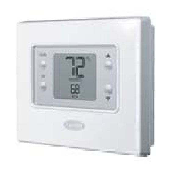
PTACSTAT ---NP---HC, PTACSTAT ---NP---HP Installation Instructions Operating Manual A07050 Non---Programmable Thermostat NOTE: Read the entire instruction manual before starting the installation. -
Page 3: Table Of Contents
Read and follow manufacturer instructions carefully. Follow all local electrical codes during installation. All wiring must conform to local and national electrical codes. Improper wiring or installation may damage thermostat. Recognize safety information. This is the safety- -alert symbol this symbol on the equipment and in the instruction manual, be alert to the potential for personal injury. -
Page 4: Introduction
Model PTACSTAT- -NP- -HP- -x is designed for HP systems, controlling one stage of cooling and two stages of heating. The HP thermostat model can be converted to an AC unit. Select the appropriate model for the intended application. -
Page 5: Installation
Battery operation is available for installations where there is no common (C) wire available at the thermostat. For battery operation, install two alkaline AA batteries. The thermostat is designed to operate up to one year on a set of batteries. A battery indicator on the display warns when battery replacement is needed. -
Page 6: Step 2 - Install Thermostat
2. If an existing thermostat is being replaced: a. Remove existing thermostat from wall. b. Disconnect wires from existing thermostat, 1 at a time. Be careful not to allow wires to fall back into the wall. c. As each wire is disconnected, record wire color and terminal marking. - Page 7 3. Open thermostat (mounting base) to expose mounting holes. The base can be removed to simplify mounting. Press the thumb release at the top of the thermostat and snap apart carefully to separate mounting base from remainder of thermostat. 4. Route thermostat wires through large hole in mounting base. Level mounting base against wall (for aesthetic value only—thermostat need not be level for...
- Page 8 6. Secure mounting base to wall with 2 anchors and screws provided (additional anchoring holes available for more secure mounting, if needed) making sure all wires extend through hole in mounting base. 7. Adjust length and routing of each wire to reach proper terminal and connector block on mounting base with 1/4 in.
- Page 9 PTAC Terminal Designations Thermostat Terminal Designations Rc - 24 VAC, from cooling equipment Rh - 24 VAC, from heating equipment W - Heating C - Common 24 VAC reversing valve G - Fan Not used Y - Cooling Fig. 3 - - Terminal Designations...
- Page 10 9. Push any excess wire into wall and against mounting base. Seal hole in wall to prevent air leaks. Leaks can affect operation. 10. Snap case back together. Attach thermostat to backplate by inserting tab on bottom edge and hinging up until top snap secures. See Fig. 4.
-
Page 11: Step 3 - Set Thermostat Configuration
2 seconds. It will be one of PH or PC (if HP, AC, H or C is displayed, the thermostat is configured incorrectly to operate a PTAC). See explanation under Step 3, Option 01 below. A heat pump thermostat, configured to operate a HeatCool unit (see Option 1 below), will display PC. A HeatCool thermostat cannot be configured to operate a HeatPump unit. - Page 12 Configuration Options - - Selection: Option 01 - - Equipment type A PTAC HeatPump thermostat (PTACSTAT- -NP- -HP- -x), valid selections are PH or PC - - Default is PH. A PTAC HeatCool thermostat (PTACSTAT- -NP- -AC- -x), the only valid selection is PC - - Default is PC.
- Page 13 C — Thermostat output (O/B) will have 24VAC in cooling mode, 0VAC in heating mode. H — Thermostat output (O/B) will have 0VAC in cooling mode, 24VAC in heating mode.
- Page 14 Selections: 01 through 06 — Default is 02. Sets the minimum allowable number of degrees between heating and cooling setpoints. One setpoint will “push” the other to maintain this difference. Option 13 - - Room Air Temperature Offset Selections: - -5 to 5_ F — Default is 0. This option selects the number of degrees F to be added to the displayed temperature to calibrate or deliberately miscalibrate the measured room temperature.
- Page 15 Selections: ON, OF — Default is OF. When ON is selected and the thermostat is not battery operated, a low level continuous display backlight is always on. With OF selected, the backlight is only on for a short time after a key is pressed.
-
Page 16: Step 4 - Check Thermostat Operation
Selection: See below — There is no default. Use this capability to reset the thermostat to “out of the box” conditions. NOTE: All previous configuration settings will be lost! When this option is selected, the configuration number (99), will appear on the large upper display and 10 will appear on the lower. - Page 17 Em Heat (HP only) To terminate the Installer Test mode, press the up or down temperature buttons. If the thermostat is left in Installer Test mode, it will revert back to normal operation after 15 minutes. Checklist 1. Run equipment through several heating and cooling cycles to ensure proper operation.
-
Page 18: Operating The Thermostat
OPERATING THE THERMOSTAT NOTE: Should the thermostat lose power, it will turn back on with the last settings prior to the power outage. Button Identification A08088 Fig. 5 - - Button Identification a - - FAN Selects whether the fan operates continuously (on) or in cycle mode... - Page 19 The display has two levels of lighting, high level and continuous low level. High level lighting comes on for 10 seconds any time a button is pressed. Continuous low level lighting is only available if the thermostat is operated from 24VAC. It is not available with batteries. Continuous low level backlighting is a configurable option (see configuration settings above).
- Page 20 Setting the temperatures for heating and cooling Your thermostat is installed with the heating set at 68_F and the cooling set at 72_F. You can use these or change them so your room is as warm or as cool as you would like it to be.
-
Page 21: Installing Or Replacing The Batteries
Turn the unit off To use the thermostat to turn off the heating and cooling system, press the mode button on the left repeatedly until the display shows off in the upper left. Installing or replacing the batteries NOTE: Remember, batteries are only required if there are not enough wires to connect a common wire. - Page 22 They are located in the back of the thermostat, so you’ll have to remove it from the wall. Here’s how to replace batteries: 1. Locate the latch at the top of the thermostat. It’s at the center of the top rim.
-
Page 23: Trouble Shooting
The battery icon appears on the display only when the battery starts to lose power. Replace it when one- -third of the icon is black. If your thermostat is battery powered and you wait until the icon is just a silhouette with no black bars, you will slowly lose thermostat functions until it doesn’t work at all. - Page 24 Here are the possible system error messages and what they mean: - -- - The room air sensor reports that the room air temperature is above 150_F or below - -50_F. E4 The memory has failed and the thermostat will return to the factory settings.
-
Page 25: Warranty
FOLLOW THESE STEPS IN ORDER: FIRST: Contact the installer. SECOND: Contact the nearest distributor. (See telephone yellow pages.) THIRD: Contact: Carrier Corporation PTAC Consumer Relations P.O. Box 4808 Syracuse, New York 13221 Phone: 1- -800- -894- -6449 Model No. Unit Serial No. -
Page 26: Warranty Conditions
(if any) of this document. LEGAL REMEDIES - - The owner must notify the Company in writing, by certified or registered letter to Carrier Corporation, PTAC Consumer Relations, P.O. Box 4808, Syracuse, New York 13221, of any defect or complaint with the... - Page 27 period begins ninety (90) days from the date of product manufacture (as indicated by the model and serial number). LIMITATIONS OF WARRANTIES: ALL IMPLIED WARRANTIES AND/OR CONDITIONS (INCLUDING IMPLIED WARRANTIES OR CONDITIONS OF MERCHANTABILITY AND FITNESS FOR A PARTICULAR USE OR PURPOSE) ARE LIMITED TO THE DURATION OF THIS LIMITED WARRANTY.
- Page 28 breakers, or damages due to the inadequacy or interruption of electrical service. 7. Damage as a result of floods, winds, fires, lightning, accidents, corrosive environments or other conditions beyond the control of Company. 8. Parts not supplied or designated by Company, or damages resulting from their use.
- Page 29 cooling. It may be useful in checkout or troubleshooting. Table 1 – Outputs EQUIPMENT COOL CONFIGURATION OPTION #1 STAGE 1 Y, G Y, G, O/B RVS = C (O) RVS = H (B) --- PTAC HEAT HEAT EM HEAT STAGE 1 STAGE 2 --- --- --- ---...
-
Page 30: Wiring Diagrams
Thermostat 52MPTAC GL or GH Fig. 7 - - A/C Thermostat Typical Installation 52MPTAC Thermostat Reversing Valve Heat Cool GL or GH 24VAC Heating 24VAC Cooling Common Fig. 8 - - HP Thermostat Typical Installation A08096 A08097... -
Page 31: Thermostat Configuration Record
Configuration Options Option 01 ____ Equipment Type Option 03 ____ Fahrenheit/Centigrade Selection Option 04 ____ Unused for PTAC Option 07 ____ Unused for PTAC Option 10 ____ Reversing Valve Option 11 ____ Minimum Deadband Between Heating and Cooling Setpoints Option 13 ____ Room Air Temperature Offset Adjustment Option 16... - Page 32 Copyright 2008 Carrier Corp. S 7310 W. Morris St. S Indianapolis, IN 46231 Printed in U.S.A. Edition Date: 03/08 Catalog No: PTACSTAT ---NP---01SI Manufacturer reserves the right to change, at any time, specifications Replaces: NEW and designs without notice and without obligations.
Need help?
Do you have a question about the PTACSTAT-NP-HP and is the answer not in the manual?
Questions and answers