Table of Contents
Advertisement
Quick Links
Advertisement
Table of Contents

Related Manuals for KDF Plus Series


Summary of Contents for KDF Plus Series
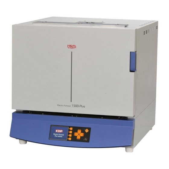
- Page 1 Thank you for purchasing KDF’s Electric Furnace Plus series. Before using the unit, please read the manual thoroughly and understand the capabilities and proper usage for this machine. Please keep this manual in an easily accessible location for future reference.
-
Page 3: Table Of Contents
Safety Precautions Before you start using your furnace Accessories Descriptions of Component Parts ■Furnace Front ■Furnace Rear Precautions before use ■About heat-treated products ■Insulation material ■Regular operating temperature and maximum operating temperature ■Operating at low temperature ■Heating element ■Structure of the furnace door ■Transportation Handling method Installation of this machine... - Page 4 ■How to program ◆Pattern selection ◆Pattern name input ◆Input of other items ■Program one point ◆Delete segment ◆Segment insertion and deletion ◆Erase pattern ◆Set item screen page move ◆Copying segment ◆PID group setting ◆Soak stop setting Copy mode Operation mode ◆Explanation of main display ◆Explanation of operation keys ■Operation during driving...
-
Page 5: Safety Precautions
We recommend you to follow these instructions for proper use of the unit. The safety precautions contained herein and the accompanying icons provided for the safe use of this machine and to prevent injuries and loss on material resources. Please read them carefully prior to your actual machine operation. Failure to follow or ignorance of the directions may WARNING cause severe injury or death. - Page 6 If any of the following situations occur, immediately turn off the power switch and breaker of this machine to cut off the power supply and contact your dealer. Continued use may cause fire or electric shock. ●When an abnormality such as smoke, a strange odor, or a noise occurs. WARNING ●If water gets inside.
- Page 7 ●Be sure to turn off the breaker of this machine for safety when you do not use this machine for a long time. ●Do not operate the machine with wet hands. It may cause electric shock. CAUTION ●Do not pull the power cord when unplugging the power plug. The cord may be damaged, causing fire or electric shock.
-
Page 8: Before You Start Using Your Furnace
When you unpack the unit, we recommend you to make sure that the following standard accessories are included. In addition, check the unit for any damage or dent on the unit surface. Contact the dealer if there is any damage on the unit. ※The heat insulation material in the furnace may crack during delivery and during use, but this is not a defect. -
Page 9: Descriptions Of Component Parts
■Furnace Front ※The drawing below shows the 1500 Plus figure as a representative. ⑦ ① ② ③ ⑤ ⑥ ④ ①Door Knob :Pull the knob to open the door and push to close. ②Furnace door :The door of the furnace body. ③Power switch (side) :To turn on the power. -
Page 10: Furnace Rear
■Furnace Rear ※The drawing below shows the 1500 Plus figure as a representative. ① ② ③ ⑩ ④ ⑥ ⑪ ⑦ ⑨ ⑧ ⑤ :Eyebolt for fixing this machine. Use wires to secure it to a sturdy ①Eyebolt structure such as a wall to prevent it from falling. ②Fan intake port :The intake port for the cooling fan. -
Page 11: Precautions Before Use
■About heat-treated products When heat-treated in an electric furnace, the physical properties may change depending on the object, which may cause a danger to the surroundings and may adversely affect the electric furnace itself. Please read the following carefully. Do not process substances that generate explosive gas by heat treatment WARNING with this machine. -
Page 12: Operating At Low Temperature
■Operating at low temperature Generally, due to the structure of electric furnaces, temperature control and temperature distribution tend to worsen as the operating temperature decreases due to control methods. When used below 300℃, the lower the temperature, the greater the tendency. Therefore, adjust the set temperature according to the actual firing condition. -
Page 13: Handling Method
Installation of this machine ■Installation location/environment ・In order to operate the muffle furnace normally, please prepare the following power supply equipment according to the product. 300Plus :AC100V 50/60Hz, current capacity 20A 500Plus :Single-phase AC200V 50/60Hz, current capacity 20A 1500Plus :Single-phase AC200V 50/60Hz, current capacity 30A 3000Plus :Single-phase AC200V 50/60Hz, current capacity 40A 5000Plus :Single-phase AC200V 50/60Hz, current capacity 50A ・Install in a place with little dust and near the power supply facility. -
Page 14: Connection Of Rear Terminals
■Connection of rear terminals ・There are terminals on the back of the main unit for exchanging signals with external devices. Please use if necessary. ◆T.C. OUTPUT (OPTION) (optional thermocouple output) ・By installing an optional temperature sensor, you can monitor the furnace temperature with a recorder. The red terminal is the + pole and the black terminal is the-pole. -
Page 15: Remote Input
◆REMOTE INPUT (remote input terminal) ・Used for remote control of this unit with a sequencer, etc. For the ON input, apply 5 to 24 VDC between COM and each signal for 1 second or longer. The course is selected in binary, and each bit is turned ON/OFF. The operation is similar to the operation from the operation panel. -
Page 16: Turn On The Power
Turn on the power ・Turn on the overcurrent breaker on the back of this machine and turn the power switch on the right side upward. ・After displaying the following screen, it shifts to the standby mode. control software version Screen data version model display Program controller operation overview The program controller can be operated automatically by programming the temperature control, each... -
Page 17: Standby Mode
Standby mode ・When the power is turned on, the title screen is displayed, then the following screen is displayed, and the unit enters standby mode. You can switch to each mode by operating in this mode. Up/down/left/right direction Key ◆Explanation of main display ・Pattern name :The name set for the selected pattern is displayed. -
Page 18: Program Mode
Program mode ・Press the "F1" (program) key in standby mode to switch to this mode. In this mode, each operation can be programmed. ◆Explanation of main display ・ 「-」display :Indicates the unprogrammed status. ・Yellow frame :The cursor position. You can change the values in this frame. ◆Explanation of operation keys ・F1(Return)... -
Page 19: Program Operation Overview
■Program operation overview This machine can be operated automatically by pre-programming the temperature control, gas control and output control. An example program is shown below, and pattern 17 will be programmed based on this. Pattern Name:KDF PLUS Temp. Time Buzzer GAS1 ℃... -
Page 20: How To Program
“UP” or “DOWN”. Press the key to select the character (number, alphabet, symbol) you want to enter. In our example, we type KDF PLUS (Screen 1). 3. When input is complete, press the down key to return the cursor to "Seg0". -
Page 21: Program One Point ◆Delete Segment
■Program one point ◆Delete segment ・If "----" is set for the temperature setting, the segment for which "----" is set and subsequent segments will be erased when returning to the standby mode with the return key. ◆Segment insertion and deletion ・Pressing the Up key while holding down the Multi key inserts a new segment at the cursor position. -
Page 22: Operation Mode
Operation mode ・Press the START/STOP key in standby mode to switch to this mode. When this mode is entered, the operation of the pattern selected in standby mode starts. ・If you insert an SD card before starting operation, the operation contents will be recorded automatically on the SD card. -
Page 23: Explanation Of Operation Keys
◆Explanation of operation keys ・F1 (Program) :Switches to the program change mode during operation. ・F2 (Switch the display) :Switches between remaining time display TOTAL (total operation time) and Seg unit. ・F3 (A/T start) :Starts PID constant auto-tuning. Press during auto tuning to cancel. ・F4 (Skip) :Set the path of the segment. -
Page 24: Operation Record Data
◆Operation record data ・Record file name: PAT05_8.csv (It will be a csv format file) "05" is the pattern number of the operation and "_8" is the serial number of pattern 05. The serial number is incremented each time the operation of pattern 05 is started and recorded with that file name. -
Page 25: Back Light" Setting
◆"Back Light" setting ・Set the LCD backlight off time. If no key is operated for the set time, the backlight turns off. Also, if you press any key while the light is off, it will return. If you set 0 minutes, it will not go out. Setting range:0 to 120 minutes Initial value:0 minutes ◆"Sensor Type"... -
Page 26: Explanation Of Main Display
◆Explanation of main display ・Energization time :The energization time at the temperature displayed on the screen is displayed in units of 0.1 hours. :Displays the number of occurrences of each error number. ・Error ■PID edit mode ・Press the "F2" (PID edit) key in the maintenance mode to switch to this mode. In this mode, PID constants can be edited for each PID number, and the constants can be written to and read from the SD card. -
Page 27: Explanation Of Operation Keys
◆Explanation of operation keys :Memorize the setting contents and shift to the standby mode. ・F1(Standby) ・F2(SD output, input) :PID constants can be output and input to the SD card. While holding down this key, use the right direction key to output and the left direction key to input. -
Page 28: Export Confidential Information
◆Export Confidential infomation ・If an error occurs, please send the exported file to us and we will let you know the details of the error and your usage. Since you can see the usage situation, you can respond more accurately. ・Insert the SD card into the slot and press the F3 key. -
Page 29: Specifications
External dimensions/weight 300Plus :314 (W)×396 (H)×468 (D) mm 22kg 500Plus :415 (W)×441 (H)×503 (D) mm 33kg 1500Plus :510 (W)×520 (H)×608 (D) mm 49kg 3000Plus :600 (W)×604 (H)×748 (D) mm 82kg 5000Plus :670 (W)×734 (H)×883 (D) mm 118kg Effective size in furnace/ 300Plus :120 (W)×110 (H)×222 (D) mm 2.9L... - Page 30 Applicable model 5000 Plus Flowmeter Nitrogen 20L/min (Oxygen, argon possible) 2 inlets ※Please contact us regarding two gas introduction units. Deodorizer Model :KDF-ES71 Applicable model 300Plus Power supply AC100V 300VA Model :KDF-ES72 Applicable models 500Plus, 1500Plus, 3000Plus, 5000Plus Power supply...
- Page 31 Smoke exhaust device Model :KDF-VF71 Applicable model 300Plus Power supply AC100V 34VA/50Hz 37VA/60Hz Accessories φ75 heat-resistant duct 2.5m (when extended) Duct clamp Model :KDF-VF72 Applicable models 500Plus, 1500Plus, 3000Plus, 5000Plus Power supply AC200V 34VA/50Hz 37VA/60Hz Accessories φ75 heat-resistant duct 2.5m (when extended)...
Need help?
Do you have a question about the Plus Series and is the answer not in the manual?
Questions and answers