Table of Contents
Advertisement
Quick Links
Instruction Manual
Thank you for purchasing the Master Plus. Before using the Master Plus, please read
the manual thoroughly and understand the capabilities and proper usage for this machine.
Please keep this manual in an easily accessible location for your future reference.
Contents
Safety Precautions ꞏꞏꞏꞏꞏꞏꞏꞏꞏꞏꞏꞏꞏꞏꞏꞏꞏꞏꞏꞏꞏꞏꞏꞏꞏꞏꞏꞏꞏꞏ 1
Standard Accessories ꞏꞏꞏꞏꞏꞏꞏꞏꞏꞏꞏꞏꞏꞏꞏꞏꞏꞏꞏꞏꞏꞏꞏꞏꞏꞏꞏ 3
Descriptions of Component Parts ꞏꞏꞏꞏꞏꞏꞏꞏꞏꞏꞏꞏ 4
Precautions before use ꞏꞏꞏꞏꞏꞏꞏꞏꞏꞏꞏꞏꞏꞏꞏꞏꞏꞏꞏꞏꞏꞏꞏꞏꞏ 6
Operation ꞏꞏꞏꞏꞏꞏꞏꞏꞏꞏꞏꞏꞏꞏꞏꞏꞏꞏꞏꞏꞏꞏꞏꞏꞏꞏꞏꞏꞏꞏꞏꞏꞏꞏꞏꞏꞏꞏꞏꞏꞏꞏ 9
Periodic Machine Cleaning ꞏꞏꞏꞏꞏꞏꞏꞏꞏꞏꞏꞏꞏꞏꞏꞏꞏꞏꞏꞏ 23
Maintenance Part Replacements ꞏꞏꞏꞏꞏꞏꞏꞏꞏꞏꞏꞏ 24
Error Messages ꞏꞏꞏꞏꞏꞏꞏꞏꞏꞏꞏꞏꞏꞏꞏꞏꞏꞏꞏꞏꞏꞏꞏꞏꞏꞏꞏꞏꞏꞏꞏꞏꞏꞏ 26
Specifications ꞏꞏꞏꞏꞏꞏꞏꞏꞏꞏꞏꞏꞏꞏꞏꞏꞏꞏꞏꞏꞏꞏꞏꞏꞏꞏꞏꞏꞏꞏꞏꞏꞏꞏꞏꞏꞏ 27
W1015000-6
Advertisement
Table of Contents

Related Manuals for KDF MASTER PLUS


Summary of Contents for KDF MASTER PLUS
-
Page 1: Table Of Contents
Instruction Manual Thank you for purchasing the Master Plus. Before using the Master Plus, please read the manual thoroughly and understand the capabilities and proper usage for this machine. Please keep this manual in an easily accessible location for your future reference. -
Page 2: Safety Precautions
Safety Precautions We recommend you to follow these instructions for proper use of the unit. Directions The safety precautions contained herein and the accompanying icons provided for the safe use of this machine and to prevent injuries and loss on material resources. Please read them carefully prior to your actual machine operation. - Page 3 ●In the event when there is smoke, abnormal odors or sounds, turn off the power, unplug immediately and contact the dealer for repairs. ●In the event when water enters the machine, turn off the power, unplug immediately and contact the dealer for advice. Continued use may cause electric shock or fire. ●In the event when debris enters the machine, turn off the power, unplug immediately and contact the dealer for advice.
-
Page 4: Standard Accessories
Standard Accessories When you unpack the machine, we recommend you to make sure that the following standard accessories are included In addition, please check the machine for any damage or dent on the unit surface. Contact the dealer if there is any damage on the unit. Firing Stand 1pc Firing Tray Kit 1set Ceramic Tray Stand 1pc... -
Page 5: Descriptions Of Component Parts
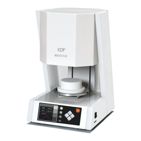
Description of Component Parts ●Front View Firing Stand Firing Table LCD Panel Start/Stop button Power Switch Function Key, from F1 to F4 Arrow Keys Firing Stand :A firing stand used to place the firing tray and firing objects. Firing Table :A table used to place the firing stand, move up/down. - Page 6 ●Backside View Pump Fuse Main Fuses Power Cord Pump Outlet Pump Hose Nipple Hook Main Fuses :Main fuses for the unit. Φ10.3-30A glass fuse. Pump Fuse :Vacuum pump fuse. Φ5.2-10A over current fuse. Pump Outlet :220-230V vacuum pump outlet. (Max. 400VA) Pump Hose Nipple :Nipple that connects the pump hose.
-
Page 7: Precautions Before Use
Precautions before use Location & Environment ・Set up the unit on the center of a flat stable table. ・Leave a minimum 10cm of space around the unit. Keep the unit away from walls and other equipment. Hook Do not place anything on the top of the unit. ・Secure the unit with the hook on the back of the unit to prevent turnover or drop. - Page 8 Installation of Ceramic Stand ・Press the button to lower the table. ・Place the provided ceramic stand at the center of the firing table. Altitude Setting ・When using the unit, please set the altitude according to your geographic location. ・For users using at high altitude, storms approaching may cause vacuum trouble. Please follow the process listed below.
- Page 9 ⑤ When the firing process is finished, the screen below will appear. Please press the “Cancel” button. The unloaded muffle firing process is complete.
-
Page 10: Operation
Operation Standby Mode ・ After powering on, the unit start display will appear and go into standby mode. It is possible to access other modes from the standby mode. Please see the following instruction for the standby mode below. Porcelain name is displayed. 1. - Page 11 ・Up/Down Operation of Firing Table:Press the buttons to move the table up/down and press buttons once again to stop moving up/down. ・Course Change:Press the button to change the course. It is possible to fast-forward the course number by pressing the buttons.
- Page 12 Program Mode ・This unit has 500 courses(course No.0 to 499) of 1 step firing program and 30 courses(course No.500 to 529) of 2 step firing program. 2 step firing program is able to fire 2 step of temperature rising and firing. ・Programmable parameters and program instructions Parameter Programmable Values...
- Page 13 -0.92 -0.90 -0.88 -0.86 -0.84 -0.82 -0.80 -0.78 ・How to program:We will program the following parameters on course No.225 to store the example. Porcelain Name KDF PLUS Vacuum -96% Start Temperature 550℃ Dry Time 3:00 Muffle Dry 0:00 Vacuum Temperature 550℃...
- Page 14 How to access to program mode:Press the “Program” button during standby mode. You can input values by table type or graph type in Program mode. You can choose whichever you like. Default setting is "Graph" type. You can switch the type of program mode in "Default Set Mode". Program mode (graph type) Standby mode Program mode (table type)
- Page 15 How to select program course ① Change the function of F2 to F4 key by Pressing the F1 ”Function” key , and Press F4 “Course Change” key to move to course select mode. ② Once the course select mode is displayed, press the F1 “▲PAGE”...
- Page 16 Subprogram Mode ・Subprogram mode:The subprogram mode is available in normal mode for additional setting. Listed below is the setting instruction and program procedure, set according to your intention. Holding Start Temperature: No, Yes Set whether or not to hold the start temperature Default:Yes Recovery Setting of Vacuum (RSV):...
- Page 17 ・How to access to subprogram mode:Press F1 “Function” button to change the function assigned F2 to F4 buttons, and press “Sub” button during program mode to move to subprogram mode. Press Press ・How to input values:Press the button to move to each values and press the ▲▼ button change the values.
- Page 18 ・Firing Mode Display Each Process Lamp Night/Day Mode Display:When setting day mode, the will appear. When setting night mode, the will appear. Each Process Lamp :While processing, each process lamp will blink. Function Button :Press the “Function” buttons to move to each mode. ・Skip button:Press this button to pass the process.
- Page 19 Manual Mode ・Please use this mode to program firing temperature, vacuum level and temperature rise manually. ・We will program the following parameters for example. Firing Temperature 870℃ Vacuum Level 97% Heat Rate 50℃/min How to access manual program mode:Press the “Manual” button during standby mode to access to manual mode.
- Page 20 ⑤ Press the “Program” button during operation to change parameters. Please see page 18 for more information. Press the “Program Cancel” button to return the operation screen. ⑥ Press the “Start/Stop” button to finish the firing. ・How to exit manual mode:Press the “Standby” button during manual mode to move to standby mode. ・Programmable parameters and program instructions for manual mode Parameter Programmable Values...
- Page 21 ④ Once the copy is finished, the screen shown below will be displayed. ⑤ Press the “Back” button to move to program mode or stop the copy. Dry Mode ・Dry Mode:This unit has a dry mode to prevent moisture inside the muffle. By running this mode when not in use during work or during the night will prevent moisture.
- Page 22 ② Finish chime Set the sound volume when firing is finished and when an error happens. ③ Other chime Set the sound volume when the unit is powered on and when it reaches start temp. Altitude :Set according to the altitude of the location when this unit is being used. See the “Altitude Setting”...
- Page 23 When the check is done, depending on the result the screens shown below will be displayed. If it is NG, check if the altitude setting is set correctly in default set mode (→P20). If the cause might be due to moisture, run the “Unloaded Muffle Firing” (→P7) and check one more time.
-
Page 24: Periodic Machine Cleaning
Periodic Machine Cleaning Please perform the following cleanings on a weekly basis. In case of a periodic machine cleaning, unplug the power cord from power outlet. If cleaning the exterior of unit, dilute mild detergent and blot with soft cloth. Firing Table When the muffle and firing stand is cold, remove the firing stand and wipe with alcohol. -
Page 25: Maintenance Part Replacements
Maintenance Part Replacements Make sure that main power is off and muffle heat is sufficiently low before you start. This may cause fire or electric shock. Drawing 1 Left Cover Right Cover Temperature Sensor Replacement 1. Remove the 4 screws shown on drawing 1 to remove the left cover and right cover. - Page 26 Muffle Replacement 1. Remove the temperature sensor. See the “Temperature Sensor Replacement” for more information. Drawing 1 Screws 2. Remove the 2 screws shown on drawing 1 to remove the white lines connected to the heater terminal. 3. Remove the 2 nuts shown on drawing 2 to remove the piping terminal.
-
Page 27: Error Messages
Error Messages When the error codes shown below are displayed, address according to the message. The following errors may sometimes be displayed in cases when there is extreme interference. Please turn off the unit and on again to see if the error code persists. Caution) When the power is turned on and is fixed, there is still a possibility that the program or default setting has been erased or the values have changed. -
Page 28: Specifications
Specifications Product name Master Plus Power requirement AC220-230V±10% 50/60Hz Power consumption 1350VA max. Overall dimensions 260(W)×432(H)×312(D) mm Weight 15.2kg Environment for setup Indoor use Room Temperature 10~40℃ Humidity 30~90%RH no condensing Altitude max. 2000m Pollution Degree 2 Over voltage Category Ⅱ...
Need help?
Do you have a question about the MASTER PLUS and is the answer not in the manual?
Questions and answers