Advertisement
Quick Links
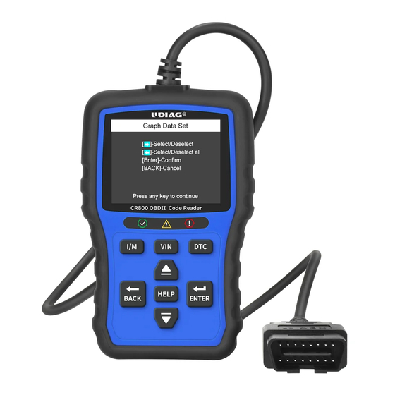
CR800 User Manual
1. Diagnostic operation
A
B
D
F
C
E
G
H
J
L
I
K
2. Before start diagnosis, please make sure
1
2
START
STOP
The ignition switch is
turned to ON position
Never try to provide power for the code reader from
USB connection when the code reader is
communicating with a vehicle.
A
OBDII Cable
Provides communication for vehicle DLC.
Green LED Display
B
Indicates the engine system is working normally.
Yellow LED Display
C
Shows the tool finds a possible problem.
Red LED Display
D
Indicates there are some problems in one or more of the
vehicle's systems.
I/M Key
E
Quick checks state emissions readiness and drive cycle
verification.
F
VIN Key
Quick checks the VIN code of vehicle.
DTC Key
G
Quick checks the DTC code.
H
UP Key
Scroll the menu.
DOWN Key
I
Scroll the menu.
BACK Key
J
Cancels an action and returns to previous screen or level.
HELP Key
K
Accesses to the Help function and it is also used to update
the code reader when long pressed.
ENTER Key
L
Confirms an action or movement and moves to next level.
3
10-14V
Engine is off
10 to 14 volt vehicle power
Don't connect or disconnect the equipments while
the ignition is on or the engine is running.
- 1 -
3. Powering up the scanner
Before using the code reader, make sure to provide power to the code reader.
The unit operates on any of the following sources:
3.1. USB connection to computer
Application platform :
win 98 to win 10
3.2. 12-volt vehicle power
a
START
STOP
Turn the ignition off.
c
START
STOP
Switch the ignition key to the ON position.
USB
b
NEAR
CENTER
OF DASH
Locate the data link connector (DLC) under the
dash on the driver side of the vehicle.
d
START
The code reader automatically boots up.
- 2 -
Advertisement

Related Manuals for UDIAG CR800

Summary of Contents for UDIAG CR800
- Page 1 CR800 User Manual 1. Diagnostic operation 3. Powering up the scanner OBDII Cable Provides communication for vehicle DLC. Before using the code reader, make sure to provide power to the code reader. Green LED Display The unit operates on any of the following sources: Indicates the engine system is working normally.
- Page 2 Before updating, please make sure your network works correctly and download the Selects battery icon in the menu to test and read the voltage of battery. www.udiagtech.com UDIAG updater from our website: 4.1. Double click UDIAG updater. 4.2. Click Setting and select the language you want to update.
Need help?
Do you have a question about the CR800 and is the answer not in the manual?
Questions and answers