
Related Manuals for Sisu Commercial Products Sleeptight 800


Summary of Contents for Sisu Commercial Products Sleeptight 800
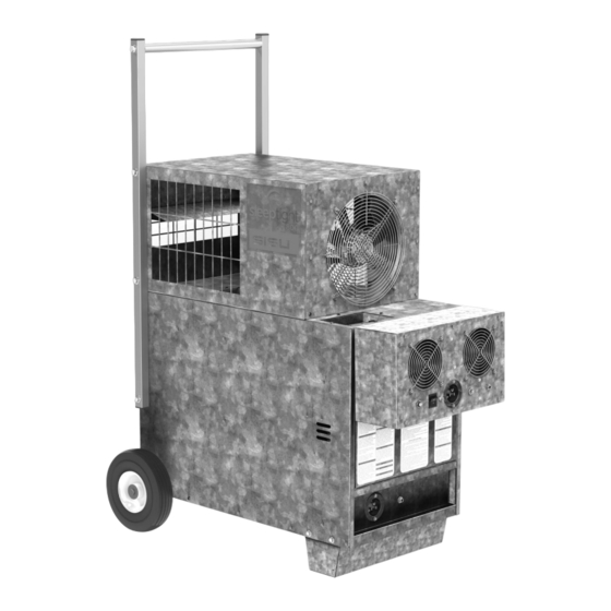
- Page 1 Sleeptight 800 OWNER’S MANUAL AND INSTRUCTIONS 80,000 Bth / 23.4 kW PS080 LP Vapor Withdrawal Report No: 0545GH006S 150-133029 REV.A...
- Page 2 Sisu Commercial Products, LLC has a continuous product improvement program; it reserves the right to change design and specifications without notice.
-
Page 3: Table Of Contents
TABLE OF CONTENTS General Hazards ..............3 Hazard Summary ..............4 Air Quality Warning .............. 5 System Description ............... 6 Specifications ............... 6 Foot/Wheels/Handle/Hose Hanger Installation ....7 Qualifications for Service & Operation ......10 General Operating Instructions ......... 12 System Components ............ -
Page 4: General Hazards
GENERAL HAZARDS GENERAL HAZARD WARNING: WARNING: Failure to comply with the precautions and Fire, burn, inhalation, and explosion instructions provided with this heater can hazard. Keep solid combustibles, such as result in death, serious bodily injury and building materials, paper, or cardboard, property loss or damage from hazards of a safe distance away from the heater as fire, explosion, burn, asphyxiation, carbon... -
Page 5: Hazard Summary
HAZARD SUMMARY Hazard Identification – Warnings, Cautions and Notices appear in appropriate sections throughout this Owner’s Manual. Read these carefully! WARNING - Indicates a potentially hazardous situation which could result in death or serious injury. CAUTION - Indicates a potentially hazardous situation which may result in minor or moderate injury. -
Page 6: Air Quality Warning
AIR QUALITY WARNING WARNING Air Quality Hazard • Do not use this heater for heating human living quarters. • Use of direct-fired heaters in the construction environment can result in exposure to levels of CO, CO2, and NO2 considered to be hazardous to health and potentially life threatening. •... -
Page 7: System Description
SYSTEM DESCRIPTION The Sleeptight 800 is designed for indoor use only. It is intended for use in providing portable, temporary heat to buildings under construction, alteration or repair. Adequate ventilation must be provided while heater is operating. Combustible solids, such as building materials, paper or cardboard must be kept at the minimum distance from the heater as shown in the table below. -
Page 8: Foot/Wheels/Handle/Hose Hanger Installation
FOOT/WHEELS/HANDLE/HOSE HANGER INSTALLATION Remove all boxes from heater and lay them out on a flat surface. Ensure all bolts are securely tighten when completed. DO NOT over tighten the bolts, damage to rivnut may occur. LEG INSTALLATION 1. Place the foot inside the heater base as shown in figure below. 2. - Page 9 HANDLE INSTALLATION 1. Assemble handle together using the provided spacers and 5/16-18 x 1 3/4” bolts. See figure below for details. NOTE: Ensure handles are Flat Washer positioned as shown. Spacer Bolt Stand-Off Screw 2. Secure the handle to the heater with provided bolts, 5/16-18 x 1 3/4”. HOSE HANGER •...
- Page 10 FUEL GAS ODOR Propane gas contains a man-made odorant added specifically for detection of fuel gas leaks. If a gas leak occurs, you should be able to smell the fuel gas . THAT’S YOUR SIGNAL TO GO INTO IMMEDIATE ACTION! •...
-
Page 11: Qualifications For Service & Operation
ATTENTION - CRITICAL POINTS TO REMEMBER! • If you have not been properly trained in repair and service of propane gas fueled heaters, then do not attempt to light the heater, perform service or repairs, or make any adjustments to the propane gas system. •... - Page 12 b. Installations in Canada: -- CAN1-B149.1 or CAN1-B149.2 Installation Codes -- CSA C22.1 Part 1 Standard Canadian Electrical Code. -- CSA C22.2 No.3, Electrical Features of Fuel Burning Equipment. 3. We cannot anticipate every use which maybe made of our heaters. Other standards govern the use of fuel gases and heat producing products in specific applications.
-
Page 13: General Operating Instructions
13. Multiple manifold cylinders may be required to ensure continuous supply of gas. 14. When the heater is to be stored indoors, the connection between the propane gas supply cylinder(s) and the heater must be disconnected and the cylinder(s) removed from the heater and stored in accordance with the Standard for the Storage and Handling of Liquified Petroleum Gases, ANSI/NFPA 58 or Standard CSA B149.1 Natural Gas and Propane Installation Code as appropriate. - Page 14 as well as from building materials (tar, concrete, plaster, etc.) which can aff ect safe operation and could result in property damage or injury. 5. Ensure that all accessories that shipped within the heater have been removed and installed. 6. Check all connections for gas leaks using approved gas leak detectors. Gas leak testing is performed as follows: -- Check all pipe connections, hose connections, fittings and adapters upstream of the gas control with approved gas leak detectors.
- Page 15 10. Do not use the heater in an propane liquid withdrawal system or application. If you are in doubt, contact your local fuel gas supplier. 11. The heater must be installed so as not to interfere with or obstruct normal exits, emergency exits, doors and walkways.
-
Page 16: System Components
SYSTEM COMPONENTS LP Gas Hose Assembly Fresh Air Fan Module Interconnect Cable 2-way LP Tank Manifold... -
Page 17: Gas Train And Electrical Components
GAS TRAIN COMPONENTS ITEM DESCRIPTION GAS CONTROL VALVE CSST TUBE IGNITER CABLE IGNITER... -
Page 18: Control Components
CONTROLS COMPONENTS Heater) Operator Interface (Top of Control Panel ITEM DESCRIPTION ITEM DESCRIPTION 10 AMP BREAKER RESET BUTTON POWER SUPPLY BOARD CO INDICATOR LED IGNITION CONTROL MODULE HIGH LIMIT INDICATOR LED CO MONITOR BOARD POWER INDICATOR LED N.C. RELAY, CO MONITOR, 12 VDC DIGITAL OPERATING THERMOSTAT FUSE HOLDER ROCKER SWITCH W/ LED, ON/OFF/ON... - Page 19 CONTROLS COMPONENTS Fresh Air Module Interface ITEM DESCRIPTION ITEM DESCRIPTION POWER ENTRY RECEPTACLE POWER SWITCH INTERCONNECT CABLE SOCKET POWER INDICATOR LED 5 AMP BREAKER RESET BUTTON FRESH AIR FAN...
- Page 20 Electrical Interface Locations ITEM DESCRIPTION INTERCONNECTING CABLE POWER ENTRY RECEPTACLE Operator Interface Location...
- Page 21 Fresh Air Fan Module Installation a. The Fresh Air Module can be installed in an exterior door fame, or external window opening. b. If securing the Fresh Air Fan Module to an exterior window, the module must securely be attached in a manner that prevents teh module from falling outside. WARNING: Fresh Air Fan Module may fall out of the window if not securely fastened to the window frame.
-
Page 22: Gas Connection
Gas Connection a. Ensure all manual shut-off valves on the gas hose and LP tank manifold are in the closed position. Verify the connections of all the gas fittings are tight. b. A minimum of two (2) 20 lb LP cylinders manifolded together, or one (1) 100 lb LP tank is required to operate heater. -
Page 23: Electrical Connection
d. Slowly open all the gas supply manual valve(s) and allow pressure to equalize. e. Check all pipe connections, hose connections, manual valves, fittings, and adapters upstream of the heater’s electronic gas control valve for gas leaks using approved gas leak detectors. In the event a gas leak is detected, check the components involved for cleanliness and further tighten as necessary to stop the leak. -
Page 24: Heater Start-Up/Thermostat Setup
Heater Start-Up WARNING: The gas supply hose assembly must be protected from traff ic, building materials and contact with hot surfaces both during use and while in storage. a. Turn the fresh air fan module’s POWER switch to the “ON” position. b. -
Page 25: Sequence Of Operation Overview
Sequence of Operation Overview 1. Power on the Fresh Air Fan Module. Fresh air fans run. 2. Press the rocker switch to “HEAT” on the heater unit. The circulating fan will start. 3. Thermostat closes on call for heat providing 24 VAC to Ignition Control. 4. -
Page 26: Heater Shut-Down
Heater Shut-Down a. Close the LP cylinder valve(s) and allow the heater to burn off any fuel gas remaining in the gas supply hose. b. Turn the heater rocker switch to the “OFF” position. c. Allow the heater circulating fan to continue to run for several minutes to cool the heater. d. -
Page 27: Ignition Board Troubleshooting
TROUBLESHOOTING, STATUS LIGHT LED LIGHT STATUS CAUSE OF FAILURE REMEDY Power light No voltage from outlet Correct power supply Ciruit breaker tripped Reset breaker High Limit Light High limit tripped Reset high limit CO light CO above 100 ppm Check for gas leaks, provide proper ventilation TROUBLESHOOTING, ROCKER SWITCH LED CODE... - Page 28 SERVICE INSTRUCTIONS WARNING: Burn Hazard • Heater surfaces are hot for a period of time aft er the heater has been shut down. • Allow the heater to cool before performing service, maintenance, or cleaning. • Failure to follow this warning will result in burns causing injury. WARNING: Fire and Explosion Hazard •...
- Page 29 MOTOR & FAN ASSEMBLY • Open the louvered access panel opposite the burner end of heater. 1. Disconnect the motor leads. 2. Remove the screws securing the motor mounting plate to the housing. 3. Pull the motor and fan assembly from the housing. 4.
- Page 30 IGNITER AND FLAME SENSOR ASSEMBLY The igniter is a local sense design, meaning it also serves to sense burner flame. For igniter/flame sensor location see Figure below. 1. Disconnect the high voltage cable from the igniter assembly. 2. Remove the 2 screws securing the igniter assembly to either the burner or the heat chamber •...
- Page 31 MANUAL RESET HIGH LIMIT SWITCH WARNING: Fire Hazard • Do not operate the heater with the high limit switch bypassed. • Operating the heater with the high limit switch bypassed or jumper-ed may lead to overheating, possibly resulting in a fire, with subsequent damage to the heater or property damage.
- Page 32 5. Check for electrical continuity across the switch terminals to make sure the contacts have closed. Install the red cap; reinstall back into the heater and connect the wires to the terminals. Reset Button Sensing Surface Terminal Flame Mounting Leg GAS CONTROL VALVE 1.
- Page 33 BURNER ORIFICE 1. Remove the brass compression nut securing the stainless steel flexible gas line to the elbow of the orifice holder. 2. Remove the bolt under the base securing the orifice holder and burner casting to the base. Orifi ce 3.
- Page 34 TRANSFORMER The transformer reduces main power supply voltage to 24 VAC for operation of the ignition control. Without 24 VAC from the transformer, the ignition control will not function, nor will the heater operate. Transformer GAS PRESSURE CHECKS WARNING: • Do not disassemble the gas control valve. •...
- Page 35 B. Gauge Installation 1. Locate the inlet and outlet pressure taps, see Figure below. Loosen the pressure tap screw using a 3/32 Allen key. Inlet Pressure Tap Regulator Adjustment Cap Outlet Pressure 2. Securely connect a pressure gauge to each pressure tap. 3.
-
Page 36: Fresh Air Module Wiring Diagram
FRESH AIR MODULE WIRING DIAGRAM... -
Page 37: Heater Wiring Diagrams
HEATER WIRING DIAGRAM... - Page 38 HEATER WIRING DIAGRAM...
-
Page 39: Replacements Parts & Service
REPLACEMENT PARTS Location Description 574244 HEATER BOARD, POWER SUPPY, 12VDC 574245 HEATER BOARD, CO MONITOR 574246 HEATER THERMOSTAT, DIGITAL PANEL, 120V 574247 HEATER BOARD, IGNITION CONTROL, DSI, UTEC 1016-529 WITH POST PURGE 574248 HEATER GUARD, FAN GUARD, 280mm 570304 HEATER FAN WHEEL, 8.000 X 4.875", 36 BLADE 574249 FRESH AIR MODULE... -
Page 40: Maintenance Instructions
MAINTENANCE INSTRUCTIONS An annual inspection of the heater by qualified service personnel is recommended to check for proper operation and to look for damage or degradation of any component. Any damaged or deteriorated parts should be replaced before the unit is put back into service. 1. - Page 41 Sisu Commercial Products, LLC. 5801 E. 41st St., Suite. 1005 Tulsa, OK 74135 www.sisu-ee.com...
Need help?
Do you have a question about the Sleeptight 800 and is the answer not in the manual?
Questions and answers