
Related Manuals for SeaLevel Relio R2 SYNC

Summary of Contents for SeaLevel Relio R2 SYNC
- Page 1 Relio R2 SYNC User Manual | RELIO R2 SYNC © Sealevel Systems, Inc. RELIO R2 SYNC Manual | SL9255 10/2021...
-
Page 2: Table Of Contents
OFTWARE BIOS CONSIDERATIONS ......................................... 28 APPENDIX A – HANDLING INSTRUCTIONS ..................................29 APPENDIX B – ELECTRICAL INTERFACE ....................................30 APPENDIX C – ASYNCHRONOUS COMMUNICATIONS ..............................31 WARRANTY ..............................................32 © Sealevel Systems, Inc. RELIO R2 SYNC Manual | SL9255 10/2021... -
Page 3: Introduction
Common I/O features include serial, analog and digital I/O. Sealevel’s extensive library of proven I/O circuits can be included as required to meet the specific I/O count, voltage ranges, and connector types. -
Page 4: Features
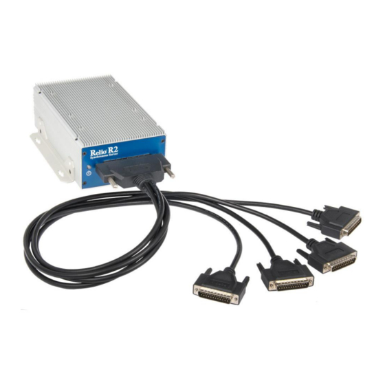
Features The following features are included and installed on the Relio R2 SYNC models. 4 Synchronous Serial ports individually configurable for RS-232, RS-422, RS-485, RS-530, RS-530A, ▪ V.35 (DB100 + Cable for 4 DB25 connectors) using the Z85230 Enhanced Serial Communications... -
Page 5: Before You Get Started
Note The lowest level of importance used to provide background information, additional tips, or other non- critical facts that will not affect the use of the product. © Sealevel Systems, Inc. RELIO R2 SYNC Manual | SL9255 10/2021... -
Page 6: Optional Items
DB25 Female (RS-530) to DB37 Male (RS-449 DTE) Cable, 10 inch Length. RS-530 was designed to replace the bulky DB37 RS-449 connector. The CA107 cable allows any Sealevel RS- 530 adapter to be used in an RS-449 application. © Sealevel Systems, Inc. - Page 7 (Item# CA178) DB25 Female (V.35) to ITU-T ISO-2593 Style Connector (V.35) Cable, 72 inch Length. The CA178 converts the Sealevel DB25 implementation of V.35 to the ITU-T V.35 mechanical standard. © Sealevel Systems, Inc. RELIO R2 SYNC Manual | SL9255 10/2021...
-
Page 8: Specifications
Width listed is for computer without mounting brackets. Total width with brackets is shown in drawings. 2 Operating temperature is dependent on particular model. See the Operating Temperature Range section for model capabilities. © Sealevel Systems, Inc. RELIO R2 SYNC Manual | SL9255 10/2021... -
Page 9: Power Supply
COM Express module, peripheral devices, and installed software. The connector at J9 is Kycon KPJX-4S. Use Kycon KPPX-4P as the mate if creating your own power cable. Figure 1 - Power Connector © Sealevel Systems, Inc. RELIO R2 SYNC Manual | SL9255 10/2021... -
Page 10: Manufacturing
Negative DC Power (GND) Positive DC Power Manufacturing All Sealevel Systems printed circuit boards are built to UL 94V0 rating and are 100% electrically tested. These printed circuit boards are solder mask over electroless Ni / Immersion gold. © Sealevel Systems, Inc. -
Page 11: System Operation
7.3728 MHz. However, other oscillator values can be substituted to achieve different baud rates. It should be noted that the Z85230 chip is manufactured in different speed ranges and installation of a different oscillator may also require changing the Z85230. © Sealevel Systems, Inc. RELIO R2 SYNC Manual | SL9255 10/2021... -
Page 12: Control And Status Registers Definition
I/O mode select. See table for valid interface options. 0 = High Impedance SD0 – SD15 Optional security feature. Unique value per customer or Default value = FFFF application. © Sealevel Systems, Inc. RELIO R2 SYNC Manual | SL9255 10/2021... -
Page 13: Interface Selection
For customers designing their own cable, the mating 100-pin connector is AMP Part# 5787169-9. The pin out for the 100-pin connector is listed below. © Sealevel Systems, Inc. RELIO R2 SYNC Manual | SL9255 10/2021... - Page 14 Port 3 Port 4 TXD- TXD+ RTS- RTS+ DTR- DTR+ TSET- TSET+ RXD- RXD+ CTS- CTS+ DSR- DSR+ DCD- DCD+ TXC- TXC+ RXC- RXC+ SHIELD Shell Shell Shell Shell Shell © Sealevel Systems, Inc. RELIO R2 SYNC Manual | SL9255 10/2021...
-
Page 15: Db-25M Connector Pin Outs
Data Set Ready Input Ground Data Carrier Detect Input Transmit Clock Input Receive Clock Input Local Loopback Output Data Terminal Ready Output Remote Loopback Output TSET Transmit Signal Element Timing Output © Sealevel Systems, Inc. RELIO R2 SYNC Manual | SL9255 10/2021... - Page 16 TDB TX+ Transmit Positive Output TXCA TXC– Transmit Clock Negative Input RDB RX+ Receive Positive Input RXCA RXC– Receive Clock Negative Input TSETA TSET– Transmit Signal Element Timing – Output © Sealevel Systems, Inc. RELIO R2 SYNC Manual | SL9255 10/2021...
- Page 17 Data Terminal Ready Negative Output Remote Loopback Output DSRB DSR+ Data Set Ready Positive Input DTRB DTR+ Data Terminal Ready Positive Output TSETA TSET– Transmit Signal Element Timing – Output © Sealevel Systems, Inc. RELIO R2 SYNC Manual | SL9255 10/2021...
- Page 18 Input Local Loopback Output RTSB RTS+ Request To Send Positive Output DTRA DTR– Data Terminal Ready Negative Output Remote Loopback Output TSETA TSET– Transmit Signal Element Timing – Output © Sealevel Systems, Inc. RELIO R2 SYNC Manual | SL9255 10/2021...
- Page 19 Output * Data Terminal Ready Output * Remote Loopback Output * TSETA TSET– Transmit Signal Element Timing – Output All modem control signals are single-ended (un-balanced) with RS-232 signal levels. © Sealevel Systems, Inc. RELIO R2 SYNC Manual | SL9255 10/2021...
-
Page 20: Cmos Battery
To fulfill the requirements of EN 60950, the R2 SYNC incorporates two current-limiting devices (resistor and diode) in the battery power supply path. System Description The following I/O connectors use industry standard pin outs for maximum compatibility. Front Panel I/O Connectors © Sealevel Systems, Inc. RELIO R2 SYNC Manual | SL9255 10/2021... -
Page 21: Rear Panel I/O Connectors
Rear Panel I/O Connectors © Sealevel Systems, Inc. RELIO R2 SYNC Manual | SL9255 10/2021... -
Page 22: Mechanical Drawings
Mechanical Drawings Top View © Sealevel Systems, Inc. RELIO R2 SYNC Manual | SL9255 10/2021... - Page 23 Flush Mounting - If the computer is to be mounted to a thermally conductive surface it is recommended to mount the computer flush to the surface to transfer heat into the structure. © Sealevel Systems, Inc. RELIO R2 SYNC Manual | SL9255 10/2021...
- Page 24 Mechanical Drawings, Continued Front View Rear View © Sealevel Systems, Inc. RELIO R2 SYNC Manual | SL9255 10/2021...
- Page 25 0.5” off the surface. This will allow additional airflow to remove heat from the bottom of the enclosure. Front view (raised) © Sealevel Systems, Inc. RELIO R2 SYNC Manual | SL9255 10/2021...
- Page 26 If no airflow is present in the application environment, orienting the computer so the heat sink fins run in the Z direction (vertically up and down) facilitates natural convection improving heat removal. © Sealevel Systems, Inc. RELIO R2 SYNC Manual | SL9255 10/2021...
-
Page 27: Getting Started
All Sealevel products are shipped with media containing the installers for each software package available. If the media is otherwise unavailable or if desired, the current versions of Sealevel software packages can be obtained from the Sealevel website (see following instructions). If you already have the Sealevel software, proceed to the Windows or Linux installation section. -
Page 28: Bios Considerations
The display should now be working. If this does not work, contact Sealevel Systems Technical support. 6. Once the computer has rebooted and video is working, it is a good idea to disable the LVDS flat panel interface. -
Page 29: Appendix A - Handling Instructions
Keep work area free of non-conductive materials such as ordinary plastic assembly aids and Styrofoam. • Use field service tools such as cutters, screwdrivers, and vacuum cleaners that are conductive. © Sealevel Systems, Inc. RELIO R2 SYNC Manual | SL9255 10/2021... -
Page 30: Appendix B - Electrical Interface
(Tx+ to Rx+ and Tx- to Rx-). Four wire mode allows full duplex data transfers. RS-485 does not define a connector pin-out or a set of modem control signals. RS-485 does not define a physical connector. © Sealevel Systems, Inc. RELIO R2 SYNC Manual | SL9255 10/2021... -
Page 31: Appendix C - Asynchronous Communications
The communication parameters are baud rate, parity, number of data bits per character, and stop bits (i.e., 9600,N,8,1). © Sealevel Systems, Inc. RELIO R2 SYNC Manual | SL9255 10/2021... -
Page 32: Warranty
In the event of failure, Sealevel will repair or replace the product at Sealevel's sole discretion. Failures resulting from misapplication or misuse of the Product, failure to adhere to any specifications or instructions, or failure resulting from neglect, abuse, accidents, or acts of nature are not covered under this warranty.
Need help?
Do you have a question about the Relio R2 SYNC and is the answer not in the manual?
Questions and answers