Advertisement
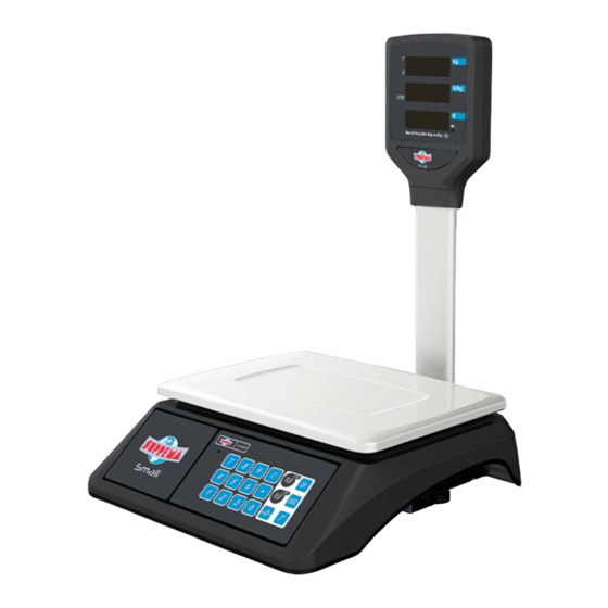
FIG.12
THE SCALE IS READY TO USE
(FIG.12) ONCE FIXED THE COLUMN WITH THE DISPLAY TO THE
BASE, CONNECT IT TO THE ELECTRICITY AND START WORKING.
Via Antiniana, 115 - 80078 Pozzuoli (NA) - Italy
Tel: (+39) 081 2428557 | Fax: (+39) 081 2428552
E-mail: commercial@ditron.eu
4
Ditron
www.ditron.eu
All information contained in this guide may be subject to changes by Suprema without notice.
SUPREMA SMALL
Assembly instructions for display column
WARNING:
the Manufacturer does not assume any liability for damage or loss caused from improper use of the product
and lack of vision of the information provided in this manual. An improper installation of the product, not in
accordance with manufacturer's instructions, may cause malfunctioning.
Before starting any maintenance intervention, make sure that the power cord is not connected.
FIG.1
FIG.3
CHECK
VERIFY THAT YOU RECEIVED ALL PARTS AND CORRECT
QUANTITY
MPD522 REV.01 02/02/2022
Thank you for choosing SUPREMA.
For more details and information visit www.ditron.eu
FIG.2
OPENING
UNPACK SMALL SCALE FROM THE
BOX (FIG.1) CHECK IF THE PAN IS ON
TOP (FIG 2) REMOVE THE
POLYSTYRENE TOP COVER
PACKAGING CONTENT
1X BASE
1X COLUMN
1X FIXING PLATE
2X SOCKET SCREWS
NECESSARY TOOLS
1X DISPLAY
1X RING
X1 POWER ADAPTER
X7 CROSS SCREWS
1
Advertisement
Table of Contents

Related Manuals for Ditron SUPREMA SMALL

Summary of Contents for Ditron SUPREMA SMALL
- Page 1 BASE, CONNECT IT TO THE ELECTRICITY AND START WORKING. Thank you for choosing SUPREMA. For more details and information visit www.ditron.eu WARNING: the Manufacturer does not assume any liability for damage or loss caused from improper use of the product and lack of vision of the information provided in this manual.
- Page 2 UPPER PART INFERIOR PART FIG.4 FIG.5 FIG.8 FIG.9 CABLE ROUTING IN THE COLUMN CONNECTION (FIG 4) BUNDLE THE ELECTRICAL CABLES OF THE DISPLAY AND INSERT THEM INSIDE THE HOLLOW (FIG.8) CONNECT THE BASE TO THE COLUMN BY ATTACHING THE TERMINALS (FIG.9) INSERT THE COLUMN (FIG 5) WE RECOMMEND TO USE A TOOL WITH A LONG LEVER AND WITHOUT A TIP COLUMN INTO THE JOINT AND STABILIZE IT BY SCREWING IN THE 2 SOCKET SCREWS FIG.6...
Need help?
Do you have a question about the SUPREMA SMALL and is the answer not in the manual?
Questions and answers