Table of Contents
Advertisement
Advertisement
Table of Contents

Related Manuals for Husqvarna MZ25 / 968999780


Summary of Contents for Husqvarna MZ25 / 968999780
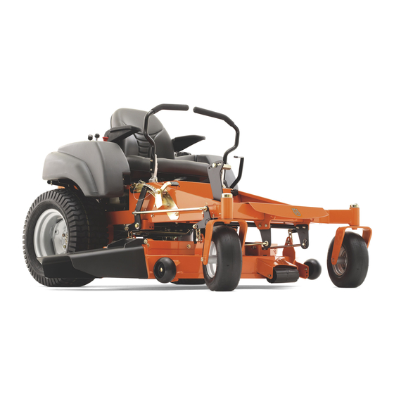
- Page 1 MZ5225 / 968999717 MZ6125 / 968999718 MZ7227 / 968999719 MZ5225BF / 968999720 MZ6125BF / 968999721 MZ5225C / 968999748 MZ6125C / 968999749 MZ25 / 968999780 Please read the operator’s manual carefully and make sure you understand the instructions before using the machine. English...
- Page 2 ©2008 HTC. All rights reserved. Beatrice, NE. Printed in U.S.A.
-
Page 3: Table Of Contents
INTRODUCTION ... 5 General ... 5 Driving and Transport on Public Roads ... 5 Towing... 5 Operating ... 5 Good Service ... 6 SyMBOlS AND DECAlS ... 7 SAFETy ... 9 Safety Instructions ... 9 General Operation ... 9 Personal Safety Equipment ... 11 Slope Operation ... - Page 4 WARNING! Failure to follow cautious operating practices can result in serious injury to the operator or other persons. The owner must understand these instructions, and must allow only trained persons who understand these instructions to operate the mower. Each person operating the mower must be of sound mind and body and must not be under the influence of any mind altering substance.
-
Page 5: Introduction
INTRODUCTION Congratulations Thank you for purchasing a Husqvarna ride-on mower. This machine is built for superior efficiency to rapidly mow primarily large areas. A control panel easily accessible to the operator and a hydrostatic transmission regulated by steering controls both contribute to the machine’s performance. -
Page 6: Good Service
Good Service Husqvarna’s products are sold all over the world and only in specialized retail stores with complete service. This ensures that you as a customer receive only the best support and service. Before the product is delivered, the machine has, for example, been inspected and adjusted by your retailer. See the certificate in the Service Journal in this operator’s manual. -
Page 7: Symbols And Decals
These symbols are found on the machine and in the operator’s manual. Study them carefully so that you know what they mean. WARNING! Xxxx xxxxxx xxxxx xxxx xxxxxxxxx xxxxxx xxxxxxxxx. xx xxxxxxxx xxxx xxxxxx. Used in this publication to notify the reader of a risk of personal injury or death, particularly if the reader should neglect to follow instructions given in the manual. - Page 8 Read Shut off engine and Operator’s remove key before Manual performing any maintenance or repair work Whole body Severing of fingers exposure to and toes thrown objects Moving sharp blades under cover English SyMBOlS AND DECAlS Keep a safe distance from the machine Do not open or remove safety...
-
Page 9: Safety
Safety Instructions These instructions are for your safety. Read them carefully. WARNING! This symbol means that important safety instructions need to be emphasized. It concerns your safety. IMPORTANT: THIS CUTTING MACHINE IS CAPABlE OF AMPUTATING HANDS AND FEET AND THROWING OBJECTS. - Page 10 • Operate machine only in daylight or good artificial light. • Do not operate the machine while under the influence of alcohol or drugs. • Watch for traffic when operating near or crossing roadways. • Use extra care when loading or unloading the machine into a trailer or truck.
-
Page 11: Personal Safety Equipment
Personal Safety Equipment WARNING! When using the machine, approved personal protective equipment (shown in illustrations) shall be used. Personal protective equipment cannot eliminate the risk of injury but it will reduce the degree of injury if an accident does happen. Ask your retailer for help in choosing the right equipment. - Page 12 • Do not use on steep slopes. • Do not try to stabilize the machine by putting your foot on the ground. • Do not mow near drop-offs, ditches, or embankments. The machine could suddenly roll over if a wheel is over the edge or if the edge caves in.
-
Page 13: Safe Handling Of Gasoline
WARNING! The engine must not be started when the driver’s floor plate or any protective plate for the mower deck’s drive belt is removed. Safe Handling of Gasoline To avoid personal injury or property damage, use extreme care in handling gasoline. Gasoline is extremely flammable and the vapors are explosive. -
Page 14: General Maintenance
General Maintenance • Never operate machine in a closed area. • Keep all nuts and bolts tight to be sure the equipment is in safe working condition. • Never tamper with safety devices. Check their proper operation regularly. • Keep machine free of grass, leaves, or other debris buildup. - Page 15 • Ensure that nuts and bolts, especially the fastening bolts for the blade attachments, are properly tightened, torqued and that the equipment is in good condition. • Do not modify safety equipment. Check regularly to be sure it works properly. The machine must not be driven with defective or unmounted protective plates, protective cowlings, safety switches, or other protective...
-
Page 16: Transport
• The blades are sharp and can cause cuts and gashes. Wrap the blades or use protective gloves when handling them. • Check the parking brake’s functionality regularly. Adjust and service as necessary. • The mulch blades should only be used in familiar areas when higher quality mowing is desired. -
Page 17: Roll Over Protection System (Rops)
Roll over Protection system (ROPS) The ROPS increases the basic weight of the unit by 42 lbs/19 kg. The ROPS is an accessory. • Do not use ROPS as a lifting, attaching or anchoring point. • Do not use ROPS for wrecking or towing. •... -
Page 18: Controls
This operator’s manual describes the Husqvarna Zero Turn Rider. The rider is fitted with a Kohler four- stroke overhead valve engine developing 25-27 horse power*. Control Locations Motion control levers Parking brake Throttle control Blade switch Ignition switch Choke control Fuses *As rated by the engine manufacturer. -
Page 19: Steering Control Levers
1. Steering Control Levers The machine’s speed and direction are continuously variable using the two steering controls. The steering controls can be moved forward or backward about a neutral position. Furthermore, there is a neutral position, which is locked if the steering controls are moved outward. -
Page 20: Parking Brake
2. Parking Brake IMPORTANT INFORMATION The machine must stand absolutely still when applying the parking brake. Always set the parking brake before dismounting. Release the parking brake before moving the mower. The parking brake is found on the left of the machine. Pull the lever backward to activate the brake and forward to release it. -
Page 21: Ignition Switch
5. Ignition Switch The ignition key is placed on the control panel and is used to start and stop the engine. 6. Choke Control The choke control is used for cold starts in order to provide the engine with a richer fuel mixture. For cold starts the control should be pulled out to its extent. -
Page 22: Fuel Tank
8. Fuel Tank Read the safety instructions before refueling. The machine has one fuel tank, just behind the seat. The tank capacity is 5.7 gallons (22 liters). Make sure the fuel cap is properly tightened and the cap gasket is not damaged. The engine will run on a minimum of 85-octane unleaded gasoline (no oil mix). -
Page 23: Fuel Shut Off Valve
9. Fuel Shut Off Valve The fuel shut off valve is located at the left rear of the seat. The valve is off when the handle tab is turned perpendicular to the fuel line. 10. Lifting Lever for the Mower Deck The lifting lever is used to transfer the mower deck from the transport position into the preferred cutting height position. -
Page 24: Hour Meter
11. Seat Adjustment Lever The seat can be adjusted lengthways. When making adjustments, the lever under the front edge of the seat is moved to the left (as seen by the driver in the seat), after which the seat can be moved backward or forward. -
Page 25: Operation
Read “Safety Instructions” section and following pages, if you are unfamiliar with the machine. Training Zero turn mowers are far more maneuverable than typical riding mowers due to their unique steering capabilities. We suggest that this section be reviewed in its entirety prior to attempting to move the mower under its own power. -
Page 26: Before Starting
Before Starting • Read the sections Safety Instructions and Controls before starting the machine. • Perform the daily maintenance before starting (see Maintenance Schedule in the Maintenance section). • Check that there is sufficient fuel in the fuel tank. • Adjust the seat to the desired position. - Page 27 Disengage the mower blades by pressing the blade switch downwards. Move the steering controls outward to the locked (outer) neutral position. Move the throttle to the middle position. OPERATION Press the control for disengaging the mower deck Place controls in neutral position Set the throttle 8061-002 8061-012b...
- Page 28 If the engine is cold, the choke control should be pulled out to its extent. Open the fuel valve. Press in and turn the ignition key to the start position English OPERATION Set the choke control Fuel valve in the OPEN position Turn to START position 8061-004 8011-438...
- Page 29 When the engine starts, immediately release the ignition key back to the run position. IMPORTANT INFORMATION Do not run the starter for more than 5 seconds each time. If the engine does not start, wait approximately 10 seconds before retrying. Set the desired engine speed with the throttle.
-
Page 30: Jumper Cables
Starting the engine with a weak battery WARNING! Lead-acid batteries generate explosive gases. Keep sparks, flame and smoking materials away from batteries. Always wear eye protection when around batteries. IMPORTANT INFORMATION Your mower is equipped with a 12-volt negative grounded system. The other vehicle must also be a 12-volt negative grounded system. -
Page 31: Running
Running Release the parking brake by moving the lever downward. NOTE: The mower is equipped with an operator presence system. When the engine is running, any attempt by the operator to leave the seat without first setting the parking brake will shut off the engine. Move the steering controls to the neutral position (N). -
Page 32: Operating On Hills
the right wheel is reduced and the machine turns to the right. Turning on the spot (zero turn) can be achieved by moving one control backward (behind the neutral position) and carefully moving the other steering control forward from its neutral position. Operating on hills Read the Safety Instructions “Driving on Slopes”... -
Page 33: Mowing Tips
Mowing Tips • Observe and flag rocks and other fixed objects to avoid collisions. • Begin with a high cutting height and reduce it until the desired mowing result is attained. The average lawn should be cut to 2½" (64 mm) during the cool season and over 3"... -
Page 34: Stopping The Engine
Stopping the Engine Allow the engine to idle a minute in order to attain normal operating temperature before stopping it, if it has been worked hard. Avoid idling the engine for longer periods, as there is a risk of the spark plugs fouling. -
Page 35: Pump Release Valves
Pump release valves IMPORTANT INFORMATION Tighten the valve moderately. Do not overtighten the valve when closing. That can damage the valve seat. Pump release valves are located at the front and rear of the pump. They are used to release the system so the machine may be moved by hand when not running. -
Page 36: Maintenance
Maintenance Schedule The following is a list of maintenance procedures that must be performed on the machine. For those points not described in this manual, visit an authorized service workshop. An annual service carried out by an authorized service workshop is recommended to maintain your machine in the best possible condition and to ensure safe operation. - Page 37 Maintenance Check/adjust throttle and choke cables Check the condition of belts, belt pulleys Change the engine oil Replace the engine oil filter Clean/replace the spark plugs Replace the fuel filter Replace the air filter (paper filter) Check the caster wheels (every 200 hours) Replace the air cleaner’s pre-filter Check/adjust the mower deck Check the engine valve clearance...
-
Page 38: Battery
Battery your mower is equipped with a maintenance free battery and does not need servicing. However, periodic charging of the battery with an automotive type battery charger will extend its life. • Keep battery and terminals clean. • Keep battery bolts tight. •... -
Page 39: Ignition System
Ignition System The engine is equipped with an electronic ignition system. Only the spark plugs require maintenance. For recommended spark plugs, see Technical Data. 1. Remove the ignition cable boot and clean around the spark plug. 2. Remove the spark plug with a spark plug socket wrench. -
Page 40: Engine Cooling Air Intake
Engine Cooling Air Intake Check that the engine’s cooling air intake is free from leaves, grass, and dirt. If the cooling air intake is clogged, engine cooling deteriorates, which can lead to engine damage. The cooling air intakes rotates when the engine is running. -
Page 41: Air Filter Maintenance
Air Filter Maintenance If the engine seems weak or runs unevenly, the air filter may be clogged. If running with a dirty air filter, the spark plugs can become fouled. For this reason, it is important to replace the air filter regularly (see the heading Maintenance Schedule for the proper service interval). -
Page 42: Replacing The Fuel Filter
Replacing the Fuel Filter Replace the line-mounted fuel filter every 100 hours (once per season) or more regularly if it is clogged. Replace the filter as follows: 1. Move the hose clamps away from the filter. Use flat-nosed pliers. 2. Pull the filter loose from the hose ends. 3. -
Page 43: Parking Brake
Visually check that no damage is found on the lever, links, or switch belonging to the parking brake. Perform a standstill test and check that there is sufficient braking action. To adjust the parking brake, contact the Husqvarna service workshop. WARNING! Faulty adjustment result in reduced braking ability and can cause an accident. -
Page 44: Deck Belt
Deck belt Deck belt removal Park on a level surface. Apply park brake.lower the deck into the lowest cutting position. Remove foot plate and belt shields. Using a ratchet with a 9/16” socket on the spring idler bolt to relieve the tension on the belt. -
Page 45: Pump Belt
Pump Belt Replacing pump belt Park the mower on a level surface. Engage the parking brake. Belt removal Remove the deck belt (see Deck Belt Removal in this section of the manual). Remove clutch stop to access the belt. Disconnect clutch wire. Create slack in the belt by removing the spring on the pump idler arm. -
Page 46: Blade Replacement
Install and tighten blade bolt securely. • Torque blade bolt to 45-55 ft/lbs (60-75 Nm). IMPORTANT INFORMATION Special blade bolt is heat treated. Replace with a Husqvarna bolt if required. Do not use lower grade hardware than specified. English MAINTENANCE 1. -
Page 47: Adjusting The Mower Deck
Adjusting the Mower Deck WARNING! Before performing any service or adjustment checklist: 1. Engage the parking brake. 2. Place the Blade switch in the disengaged position. 3. Turn ignition switch to “OFF” position and remove the key. 4. Make sure the blades and all moving parts have completely stopped. 5. -
Page 48: Anti-Scalp Rollers
Confirm measurements once again. Blade tips should be level in a side-to-side manner. In the rear, blade tips should be level to higher than side-to-side measurement. In the front, blade tips should be level to than side-to-side measurement. NOTE: This will place the mower deck in a base measurement position. -
Page 49: Cleaning And Washing
Cleaning and Washing Regular cleaning and washing, especially under the mower deck, will increase the machine’s life-span. Make it a habit to clean the machine directly after use (after it is cooled), before the dirt sticks. Do not spray water on the top of the mower deck. Use compressed air to clean the top side of mower deck. -
Page 50: Lubrication
12/12 Every year 1/52 Every Week 1/365 Every day • *Change transaxles (transmission) filters. General Remove the ignition key to prevent unintentional movements during lubrication. When lubricating with an oil can, it must be filled with engine oil. When lubricating with grease, unless otherwise stated, use a high grade molybdenum disulphide grease. -
Page 51: Lubricating The Cables
Lubricating the Cables If possible, grease both ends of the cables and move the controls to end stop positions when lubricating. Refit the rubber covers on the cables after lubrication. Cables with sheaths will bind if they are not lubricated regularly. -
Page 52: Engine Oil
Engine Oil 4. Engine Oil Filter • Drain the engine oil in accordance with the work description under the heading Engine Oil/Change Engine Oil. • Remove the oil filter. If necessary, use a filter remover. • Wipe new, clean engine oil onto the seal for the new filter. -
Page 53: Engine Oil Levels
Engine Oil Levels Check the oil level in the engine when the machine is standing level and the engine is stopped. Remove the dipstick, wipe it clean, and then replace it. Rotate dipstick counterclockwise until the cap drops down to the bottom of the threads. Take the dipstick out again and read the oil level. -
Page 54: Hydraulic Pump
Hydraulic Pump Fluid Change This transaxle is designed with an external filter for ease of maintenance. To ensure constant fluid quality levels and longer life an oil filter change interval of every 200 hours is recommended. The following procedure can be performed with the pump installed in the vehicle, and the vehicle on level ground. -
Page 55: Troubleshooting
Problem The engine will not start. The starter does not turn the engine over. The engine runs rough. The engine seems weak. The machine vibrates. TROUBlESHOOTING Cause • Blade switch is engaged. • Steering controls are not locked in the neutral position. - Page 56 Problem The engine overheats. Battery not charging. The machine moves slowly, unevenly, or not at all. Mower deck not engaging. Transaxle leaks oil. Uneven mowing results. English TROUBlESHOOTING Cause • Clogged air intake. • Engine overloaded. • Poor ventilation around engine. •...
-
Page 57: Storage
Service When ordering spare parts, please specify the purchase year, model, type, and serial number. Always use genuine Husqvarna spare parts. An annual checkup at an authorized service workshop is a good way to ensure that the machine performs its best the following season. -
Page 58: Schematics
RIGHT MOTION CONTROl lEVER lEFT MOTION CONTROl lEVER SEAT POSITION 1 - OFF English SCHEMATICS NOTES: 1. SEAT UNOCCUPIED 2. BRAKE SWITCH IN OFF POSITION 3. MOTION CONTROl lEVERS OUT SOlENOID 4. PTO IN OFF POSITION BRAKE SWITCH SWITCH ElECTRIC ClUTCH ENGINE GROUND... -
Page 59: Technical Data
Engine Manufacturer Type Power lubrication Oil capacity excluding filter Oil capacity including filter Engine oil (See viscosity diagram) Fuel Fuel tank capacity Spark plugs / gap Cooling Air filter Alternator Starter Transmission Transmission Speed and direction controls Speed forward Speed reverse Brakes Front caster tires, smooth tread Rear tires, turf pneumatic... - Page 60 Cutting Width Cutting Height Uncut Circle Number of Blades Blade length Nose Rollers Sprung Seat Hinged Arm Rests Hour Meter Blade Engagement Deck Construction Productivity Productivity Overall Dimensions Weight Base Machine length Base Machine Height Base Machine Width Overall Width, Chute Up Overall Width, Chute Down English TECHNICAl DATA...
- Page 61 Mechanical parking brake 13 x 5.0-6, 4 ply 23 x 10.5-12 15 PSI / 103 kPa / 1 bar 10 PSI / 69 kPa / .7 bar MZ25 / 968999780 Kohler Courage Pro 25 hp* Pressure with oil filter 1.6 qt / 1.7 liter 1.7 qt / 1.9 liter...
- Page 62 797 lbs / 362 kg 78" / 201 cm 42" / 107 cm 49" / 125 cm 73" / 187 cm 87" / 221 cm MZ25 / 968999780 Standard Standard Electromagnetic clutch 640 lbs / 290 kg 78" / 201 cm 42"...
-
Page 63: Accessories
Accessories Collection system Torque Specifications • Engine crankshaft bolt • Deck pulley bolts • lug nuts • Blade bolt • Standard ¼" fasteners • Standard " fasteners • Standard " fasteners • Standard " fasteners • Standard ½" fasteners When this product is worn out and no longer used, it should be returned to the reseller or other party for recycling. In order to implement improvements, specifications and designs can be altered without prior notification. - Page 64 The torque values shown should be used as a general guideline when specific torque values are not given. Grade SAE Grade 5 ft./lbs ¼ ½ ¾ ** Grade 5 - Minimum commercial quality (lower quality not recommended) Grade Grade 8.8 ft./lbs 13.5 43.5...
-
Page 65: Conformity Certificates
CONFORMITy CERTIFICATES USA requirements Labels are placed on the engine and/or in the engine compartment stating that the machine will fulfill the requirements. This is also applicable to special requirements for any of the states, (California emission rules etc.). Do not remove any of these labels. Certificates can also be supplied with the machine at delivery or written in the Engine manual. -
Page 66: Service Journal
Action Delivery Service 1. Charge battery. 2. Adjust tire pressure of all wheels according to Technical Data. 3. Mount the steering controls in the normal position. 4. Connect the contact box to the cable for the seat’s safety switch. 5. Check that the right amount of oil is in the engine. 6. -
Page 67: After The First 5-8 Hours
Action After the First 5-8 Hours 1. Change engine oil. SERVICE JOURNAl Date, mtr reading, stamp, sign English English... -
Page 68: 25-Hour Service
Action 25-Hour Service 1. Check the engine air filter. 2. Sharpen/Replace mower blades if required. 3. Check the tire pressures. 4. Check battery with cables. 5. lubricate according to lubrication chart. 6. Check/clean the engine’s cooling air intake. 7. Clean the air cleaner’s prefilter (foam). English English SERVICE JOURNAl... -
Page 69: 50-Hour Service
Action 50-Hour Service 1. Perform the 25-hour service. 2. Clean/replace the air cleaner’s filter cartridge (paper filter) (shorter intervals for dusty operating conditions). 3. Change engine oil. 4. lubricate according to lubrication chart. 5. Check/adjust the parking brake. SERVICE JOURNAl Date, mtr reading, stamp, sign English English... -
Page 70: 100-Hour Service
Action 100-Hour Service 1. Perform the 25-hour service. 2. Perform the 50-hour service. 3. Change the engine oil filter. 4. Clean/replace the spark plugs. 5. Replace the fuel filter. 6. Clean the cooling fins on the engine and transmission. 7. Check V-belts. 8. -
Page 71: 300-Hour Service
Action 300-Hour Service 1. Perform the 25-hour service. 2. Perform the 50-hour service. 3. Perform the 100-hour service. 4. Check/adjust the mower deck. 5. Clean the combustion chamber and grind the valve seats. 6. Check the engine valve clearance. 7. Replace the air cleaner’s prefilter (foam). SERVICE JOURNAl Date, mtr reading, stamp, sign English... -
Page 72: At Least Once Each Year
Action At Least Once Each Year 1. Clean the engine’s cooling air intake (25 hours). 2. Replace the air cleaner’s pre-filter (foam) (300 hours). 3. Replace the air filter’s paper cartridge. 4. Change the engine oil (50 hours). 5. Replace the engine oil filter (100 hours). 6. - Page 73 Action SERVICE JOURNAl Date, mtr reading, stamp, sign English English...
- Page 74 Action English English SERVICE JOURNAl Date, mtr reading, stamp, sign...
-
Page 76: Warranty Statement
It is the Owner’s and Retailer’s responsibility to make certain that the Warranty Registration Card is properly filled out and mailed to Husqvarna Forest & Garden Company. This card should be mailed within ten (10) days from the date of purchase in order to confirm the warranty and to facilitate post-sale service. - Page 77 P/N 539 132401 R01 03/27/08...
Need help?
Do you have a question about the MZ25 / 968999780 and is the answer not in the manual?
Questions and answers
РАЗМЕРЫ ГАЗОНОКОСИЛКИ MZ25
The dimensions of the Husqvarna MZ25 lawn mower are:
- Base Machine Length: 76 inches (193 cm)
- Base Machine Height: 42 inches (107 cm)
- Base Machine Width: 49 inches (125 cm)
- Overall Width with Chute Up: 63 inches (157 cm)
- Overall Width with Chute Down: 76 inches (193 cm)
- Weight: 780 lbs (354 kg)
This answer is automatically generated