Table of Contents
Advertisement
Quick Links
INSTRUCTION MANUAL
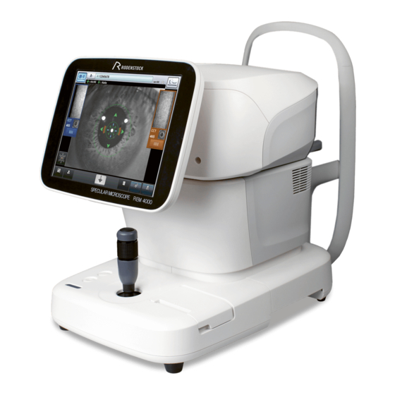
Specular Microscope
REM 4000
Read this manual thoroughly before using the instrument to
ensure proper and safe operation.
Contact Tomey Corporation or your local distributor if you
have any questions or encounter any issues during
operation.
■
Always follow the operation procedures
described in this manual.
■
Keep this manual in a readily accessible
location while operating the instrument.
■
Contact your local distributor if you lose this
manual.
603F9190-0L
Advertisement
Table of Contents

Related Manuals for Rodenstock REM 4000


Summary of Contents for Rodenstock REM 4000
- Page 1 INSTRUCTION MANUAL Specular Microscope REM 4000 Read this manual thoroughly before using the instrument to ensure proper and safe operation. Contact Tomey Corporation or your local distributor if you have any questions or encounter any issues during operation. ■ Always follow the operation procedures described in this manual.
- Page 3 i Important safety information ■ Do not install this instrument in a location where explosives or flammable substances are used or stored. Otherwise, fire or explosion may occur. ■ Do not remove the cover of the instrument. Otherwise electric shock may result. ■...
-
Page 4: How To Read This Manual
ii How to read this manual Outline This manual is structured as follows. 1. PRIOR TO USE Describes safety precautions and important information to be understood before installing and using the instrument. 2. NAMES AND FUNCTIONS Describes names and functions of each section of the instrument. 3. -
Page 5: Table Of Contents
iii Contents i Important safety information ........................i-1 ii How to read this manual ........................... ii-2 Outline ................................ii-2 Symbols used in this manual ........................ii-2 iii Contents ..............................iii-1 1. PRIOR TO USE ............................1-1 1.1 Precautions for operation ........................1-1 1.2 Checking package contents ........................ - Page 6 3.5.3 Saving ............................3-35 3.6 Database ............................. 3-36 3.6.1 Browsing examination data ......................3-36 3.6.2 Deleting examination data ......................3-37 3.6.3 Changing ID ..........................3-38 3.7 System setup ............................3-40 3.7.1 General ............................3-40 3.7.2 Measurement ..........................3-43 3.7.3 Application ............................ 3-45 3.7.4 Connection &...
-
Page 7: Prior To Use
1. PRIOR TO USE ■ Read this manual thoroughly before using the instrument to ensure proper and safe operation. ■ Always follow the operation procedures as described in this manual. ■ Check that there are no devices that generate a strong magnetic field near the instrument. - Page 8 Do not hold the head, chin rest, forehead pad, or joystick when moving the instrument. These components are detachable and the instrument may drop, resulting in injuries. Install the instrument in a location not subject to direct sunlight, high temperature and humidity, or air containing dust, salt, and/or sulfur. Otherwise, failure or malfunction may occur.
- Page 9 Do not allow any person to place their hands or fingers in the clearance under the head or the section immediately under the chin rest. Injury may result to hands and fingers. Never insert fingers or objects through the capture window. Malfunction or failure of the instrument or faulty analysis results may occur.
- Page 10 Clean the instrument at the end of operation in preparation for the next use. Clean and neatly arrange the accessories and cables. If any failure occurs in the instrument, immediately stop operation, identify the failure in the instrument, and contact your local distributor for repairs. Do not modify the instrument.
-
Page 11: Checking Package Contents
1.2 Checking package contents ■ Keep the box and packing materials for use when moving or transporting the instrument. ■ When taking the instrument out of the box, pull the outer box upward and then remove the packing materials. Be careful not to lift the instrument by directly holding the head, chin rest, forehead pad, or joystick. -
Page 12: Glossary
1.3 Glossary Percentage of cell hexagonality. [6A] Percentage of hexagonal cells in analyzed endothelium Auto Alignment / Auto Shot [AA/AS] Auto Alignment / Manual Shot [AA/MS] Average area [AVG] Average area of cells in the analyzed endothelium Capture mode in which the image selection screen appears when capturing [Basic mode] is completed. - Page 13 [Dark Area] A black circled region to be observed by specular microscope [Dark Area analysis] Analysis method to calculate values related to the Dark Area (D.A.Density, etc.) by automatically extracting Dark Areas from the captured image [L-count method] Analysis method to calculate values such as CD (cell density) according to the area and points in the cells entered by the physician [MA/MS] Manual Alignment / Manual Shot...
-
Page 14: Overview
1.4 Overview This instrument is designed to observe and analyze corneal endothelium by capturing its image without making contact, analyzing the captured image, and calculating data such as cell density. In addition, this instrument also measures the central corneal thickness while capturing an image of corneal endothelium. -
Page 15: Names And Functions
2. NAMES AND FUNCTIONS 2.1 Physician's side (1) LCD monitor and touch panel Head Displays some screens. Touch displayed buttons to operate the instrument. The tilting angle of the monitor can be adjusted. (2) Power lamp The lamp stays lit while the power is turned ON. Neck (3) Chin rest up/down button Press the button to move the chin rest up and... -
Page 16: Patient's Side
2.2 Patient's side (1) Touch pen Use this when selecting cells etc. The touch pen includes a magnet and can be attached to the side of the monitor. (2) Forehead rest and pad Have the patient lightly press their forehead to this pad to stabilize their head while capturing an image. -
Page 17: Sides Of The Main Unit
2.3 Sides of the main unit (1) Power socket (1) (2) (3) Connect the power cord here. (2) Power switch Turns the instrument on and off. (3) Packing button Holding this button for 3 seconds moves the head to a set position in preparation for packing. -
Page 18: Screen
2.4 Screen 2.4.1 Basic structure and standard items Varies depending on modes (1) Patient information button Moves to the patient information input screen. (2) Patient information field Displays the ID and name of the patient. (3) Version Displays the version of the system. (4) “Database”... -
Page 19: Capture Screen
2.4.2 Capture screen (4) (5) (6) (7) (14) (10) (11) (12) (13) (1) Eye selection button Display left or right eye according to the device head placement. Touch these buttons to move the instrument head right and left. (2) Thumbnails Display the captured images of the endothelium, anterior segment, and central corneal thickness. - Page 20 (7) Auto shot mark Shown in auto shot mode. (8) Alignment OK mark Shown when alignment is optimum. (9) Fixation light button The preset fixation light position is shown in orange on this button. Touch this button to open the Fixation screen. (10) “Setup”...
-
Page 21: Image Selection Screen
2.4.3 Image selection screen (1) Measurement eye Displays which patient’s eye (right or left) corresponds to the displayed examination data. (2) Exam Date Displays the date and time when capturing the image. (3) Thumbnails Display 8 out of 16 captured images of the endothelium as thumbnails. Images are numbered from 1 to 16 in the order of the capture quality. -
Page 22: Analysis Screen
2.4.4 Analysis screen a) R/L eye analysis screen (10) (11) (14) (15) (16) (17) (18) (12) (13) b) Single eye analysis screen (10) (11) (11) (22) (19) (14) (15) (16) (17) (18) (21) (20) (12) (13) ■... - Page 23 (1) Eye selection button Show the selected eye (right or left) by color. Touch one of these buttons to move to the single eye analysis screen. (2) ExamDate Displays the date and time when capturing the image. (3) Endothelial image Touching the image switches selection of the eye.
- Page 24 (13) “Zoom” button Enlarges the image of the endothelium. Touching this button shows the magnification adjustment bar. 100%, 200%, 400% can be selected. When the enlarged image is displayed, the image moves so that the touched point comes to the center of the frame. Touch the “Zoom”...
-
Page 25: Symbols Used For Marking
2.5 Symbols used for marking Refer to instruction manual. “ON” (power) “OFF” (power) Type B attached part Grounding (earth) 2-11 ■... - Page 26 This page is intentionally left blank. ■ 2-12...
-
Page 27: Operation Procedures
3. OPERATION PROCEDURES 3.1 Safety precautions ■ Disconnecting the power plug from the power outlet is a way to cut off power to the instrument. If there is a problem with the instrument, turn off the power switch and disconnect the power plug. Install the instrument in a place where this can be performed smoothly. - Page 28 ● PictBridge printer Insert the cable plug B (3) of the USB cable into the USB connector (PICT) (4) on the side of the main unit in the correct orientation. Connect the other cable plug A (1) of the USB cable to the printer. Refer to the instruction manual of the PictBridge printer for details on how to connect the printer.
-
Page 29: Starting/Shutting Down The Instrument
3.2.2 Starting/shutting down the instrument a) Startup Turn on the video printer and/or PictBridge printer if using these devices. Turn ON (|) the power switch of the REM 4000. - The startup screen (Fig. 2) appears and then the capture screen appears. -
Page 30: Clearing Last Examination Data (Preparation For New Patient)
3.2.3 Clearing last examination data (preparation for new patient) ■ The deleted examination data cannot be restored. Carefully check the data before deleting it. ■ Be sure to touch the “New” button to delete the examination data for the previous patient before capturing images for a new patient. Otherwise, the data for the previous patient may be included. - Page 31 (Fig.1) (Fig.2) (Fig.3) Enter necessary data. - Entry method 1: Software keyboard Patient's ID, name, sex, and date of birth can be entered using the software keyboard on the Patient Information screen (Fig. 2). If the entered ID is already recorded in the memory, the corresponding name, sex, and date of birth is automatically recalled from the memory in the main unit when the ID is entered.
-
Page 32: Patient's Eye Height Adjustment
- Entry method 5: DICOM worklist inquiry Setting “DICOM” to the system setup item “Auto Inquiry”, enables DICOM worklist inquiries. By pressing the “DICOM Inquiry” button (10) after entering the ID on the “Patient Information” screen (Fig. 5), the patient information read from the DICOM worklist in the personal computer appears. - Page 33 (Fig. 1) (Fig. 2) ■...
-
Page 34: Setting The Fixation Light Position
3.2.6 Setting the fixation light position The Fixation Light to move the patient’s eye can be turned on in the center, 6 locations in the periphery, and 6 parafovea locations. The center light is normally used for capturing images, but the peripheral and parafovea positions are effective when an image cannot be taken with the light in the center or when capturing an image at optional positions. - Page 35 2)Select the setting of each item using the corresponding buttons. - Setting items a) through d) will be described below. 3)Touch the “Exit” button (2) to close the Setup screen. a) Alignment ■ When “Manual” is selected for “Alignment”, “Auto” cannot be selected for “Shot”.
-
Page 36: How To Capture Images
3.3 How to capture images 3.3.1 Selecting eye to be measured 1)Touch the eye selection button (1) on the capture screen. (Fig. 1) 3.3.2 Alignment ■ Do not allow any person to place their hands or fingers in the clearance between the head and neck or neck and base, or the section under the chin rest. - Page 37 (Fig. 1) Perform alignment in forward and backward directions. - Touch the center of the alignment mark (3) to move the head toward the patient. Touch the head retract button (4) to retract the head toward the physician. (Fig. 2) When the cornea approaches the optimum alignment position, the focus indicator (5) appears.
- Page 38 [Fine operation] Tilting the joystick moves the head in the tilting direction. Turn the up/down ring to move the head up and down. Clockwise : the head rises. Counterclockwise : the head lowers. (Fig.2) Operate the joystick to move the head so the center of the pupil (1) appears in the center (2) of the target ring.
-
Page 39: Capturing Endothelial Images
3.3.3 Capturing endothelial images ■ Stop capturing images immediately if the patient shows any signs of photosensitive epilepsy. ■ A good image of the endothelium may not be captured, and the analysis result or corneal thickness value may become unreliable due to faulty fixing of the sight, eyelid drooping, trichiasis, corneal diseases, etc. - Page 40 (Fig. 3) (3) (4) Check the endothelial image to be captured on the live endothelial image, and touch the “Capture” button (3) or press the joystick button (2) to start capturing. - If the capture position needs to be finely adjusted, operate the joystick and adjust the position before touching the “Capture”...
-
Page 41: Selecting Image
● In Quick mode - Return to the capture screen (refer to 2.4.2) when an image for one eye has been captured. Touch the eye selection button again to capture an image for the other eye. - The R/L eyes analysis screen (refer to 2.4.4) appears when images of both eyes have been captured. -
Page 42: Analysis
3.4 Analysis 3.4.1 Auto Analysis Auto Analysis is to calculate values such as CD (cell density) by automatically extracting outlines of cells on the captured image ■ Check that the outlines of cells are correctly detected on the captured image. The outlines cannot be extracted on some images. - Page 43 ● Single eye analysis screen Touch the eye selection button (1) on the R/L eye analysis screen (Fig. 1). The single eye analysis screen (Fig. 2) appears. Distribution according to cell sizes and shapes is shown in a histogram on the single eye selection screen.
- Page 44 ● Checking central corneal thickness The measured central corneal thickness is shown on the R/L eye analysis screen and single eye analysis screen. Abbr Analysis item Unit Details eviati Central μm The thickness of the cornea at its center corneal thickness Ultrasonic μm...
- Page 45 selected on the System Setup screen. Refer to “3.7.3 Application” for setting method. The initial setting is “Area”. ● Checking fixation light position The position of the fixation light when capturing an image is shown on the R/L eye analysis screen and single eye analysis screen with icons shown below.
- Page 46 When “e” or “E” is displayed, perform any of the following actions according to the captured image condition. - Retake Capture an image again if the images are not clear. - Correcting outlines Correct and redraw the incorrect images. Refer to “3.4.1 Editing outlines”...
- Page 47 The following analysis results obtained by automatically extracting Dark Areas from the displayed image of endothelium are displayed on the Dark Area analysis screen (Fig. 4). - Dark Area analysis image Use the following buttons to change the image. Abbre Item Details viation...
- Page 48 Analysis in the Dark Area can be set to ON or OFF in “Dark Area Analysis” on the System Setup screen. - The initial setting is “ON”. - The “Dark Area” button does not appear on the single eye analysis screen if this item is set to OFF. Namely, the Dark Area analysis screen (Fig.
- Page 49 (3) Eraser button Deletes outlines shown in red. Touch the line in the image to delete it. (Fig. 4) (4) Analysis range selection button Specifies the range to be analyzed. Specify an area to be analyzed by selecting two opposing points in an area where the shape of the cell can be confirmed.
- Page 50 c) Selecting cells Cells used for analysis can be selected from endothelial cells extracted by automatic analysis. The Edit mark appears on the analysis screen when cells are selected. Refer to “2.4.4 Analysis screen” for details of edit marks. Touch the “Cell Select” button (1) on the analysis screen (Fig. 1) to open the Cell Select screen (Fig.
-
Page 51: L-Count Method
3.4.2 L-count method The L-count method is an analysis method to calculate values such as CD (cell density) according to the area and points entered by the physician a) Switching to L-count method Touch the “Method” button (1) on the analysis screen to open the Method screen (Fig. - Page 52 1) Specify the range. Touch the range selection button (4) to activate it. Touch two opposing points of the area (rectangle) subject to calculation on the image of the endothelium. When “100 μm” is set to “L-count range” of the system setup items, touch the center of the 100-μm-square frame.
- Page 53 c) How to read analysis results (Fig. 5) Three analysis values (NUM, CD, and AVG) are calculated in the L-count method. Analysis values are displayed on the analysis screen (Fig. 5). A hyphen (-) is shown for analysis values other than NUM, CD, and AVG. The analyzed image (Area, Apex) is not output.
-
Page 54: Core Method
3.4.3 Core method The Core method is an analysis method to calculate values such as CD (cell density) by extracting the outline of the cell referring to the center of the cell entered by the physician a) Switching to Core method 1)... - Page 55 (Fig. 3) Place a dot inside a cell. - Touch the cell selection button (4) to activate it. Specify the center of each cell using the touch pen. - A green dot appears at the touched point. - The “Count” field (3) increases the number of dots every time a cell is specified.
- Page 56 the Core method. Analysis values are displayed on the analysis screen (Fig. - The analyzed image (Trace, Area and Apex) is not output. - Touch the “Point Edit” button and open the Point Edit screen to edit points again. - When analyzing another eye by the Core method, touch the image of the endothelium to change the eye, touch the “Point Edit”...
-
Page 57: Export, Print, And Save
3.5 Export, Print, and Save Two functions from Export, Print, and Save can be assigned to two buttons provided at the bottom center of the analysis screen. Those functions are assigned on the System Setup screen. Refer to “3.7.4 Connection & Print” for the setting method. - Page 58 Touch the “Export” button (1) to display the Confirmation screen (Fig. 2). (Fig. 1) (Fig. 2) The transfer confirmation screen (Fig. 2) displays patient ID, name, sex, and date of birth. Touch the “Export” button (2) to start sending data. - Touching the “Cancel”...
-
Page 59: Printing
3.5.2 Printing Touch the “Print” button to start the one of the 5 following printings: built-in printer, a video monochrome printer, a video color printer, a PictBridge printer, or a network printer. Select the desired printer in the system setup. Refer to “3.7.4 Connection & Print”... - Page 60 (13) (13) Central corneal thickness (14) (14) Ultrasonic correction for central corneal thickness (15) (15) Dark area analysis value (16) (16) Dark area analysis setting (D) : Dark area analysis ON (17) (A) : Analysis as endothelium Footer (18) (17) Printing date/time (18) Character string defined by user b) Printout from video printer...
-
Page 61: Saving
3.5.3 Saving ■ Always enter the ID number before saving the examination data. ■ Turn off the instrument when inserting or removing the SD card. Inserting or removing the SD card while the instrument is on may damage the saved data. ■... -
Page 62: Database
3.6 Database 3.6.1 Browsing examination data Touch the “Database” button (1) on the analysis screen to open the Patient List screen (Fig. 2). (Fig. 1) (Fig. 2) Touch the patient list window (3) to select the patient. - The selected line turns black. - Enter a search string into the search box (2). -
Page 63: Deleting Examination Data
Select the data to be browsed using the “View 1” or “View 2” button. - The examination data selected by the “View 1” or “View 2” button is shown on the left or right side of the R/L eye view screen respectively. - Touch the “Exit”... -
Page 64: Changing Id
b) Deleting data on Exam List screen Touch the delete button (1) to delete the captured image data selected by the “View 1” and “View 2” buttons. Touch the all clear button (2) to delete all examination data of the selected patient. - Page 65 Enter the ID number and press the save button (2) to change the current examination data ID number. (Fig. 2) 3-39 ■...
-
Page 66: System Setup
3.7 System setup The “system setup” function is provided in this instrument to change various settings. “System setup” settings are retained even when the instrument is turned off. Open the System Setup screen. Touch the “System Setup” button (1) on the Setup screen (Fig. - Page 67 (2) Language Selects the language. (3) Date & Time Sets the display format of the date and the date and time. The key pad appears when the input field is touched. (4) Sound Sets whether to emit sounds when capturing an image and operating the screen.
- Page 68 examination data to TOMEY Link. Indispen- Select this when ID numbers are always required. sable Data cannot be saved or sent when the ID is not entered. Select this when the ID is usually entered, but data can also be saved and sent without entering the ID. Data is saved and sent with the ID as “No ID”...
-
Page 69: Measurement
(Fig. 2) (2) Keyboard Layout Select the software keyboard type. 3.7.2 Measurement Input settings related to capturing images. Click the “Measurement” tab. (Fig. 1) (1) Alignment Select the alignment mode: Auto or Manual. Auto The Auto Alignment function is active. Alignment in up/down/right/left/focus directions is performed automatically. - Page 70 (4) Measurement mode Sets the mode for capturing images. Quick Capture mode in which the image selection screen does not appear when capturing is completed. This mode is for users that do not need to look at all 16 images of the endothelium.
-
Page 71: Application
3.7.3 Application Make settings related to display and analysis. Select the “Application” tab. (Fig. 1) (1) Analysis Method Selects the switching method for analysis method. Set the function for the lower button 1 on the analysis screen (Fig. 2). (Fig. 2) (Button 1) (2) Fixation Sets whether to show the image capturing position on the fixation light... - Page 72 b) Auto Analysis Touch the “Setting” button (1) of “Auto Analysis” to open the System Setup screen (Fig. 2). (Fig. 1) (Fig. 2) (2) Analysis result Sets images (Photo, Trace, Area or Apex) to be shown immediately after analysis is completed. (3) Reliability Sets whether to display the reliability mark on the screen.
- Page 73 c) L-count Method Touch the “Setting” button (1) of “L-count Method” to open the System Setup screen (Fig. 2). (Fig. 1) (Fig. 2) (2) L-count Area Sets how to specify the range for analysis by the L-count method. Variable : Set the analysis range by specifying two opposing points.
-
Page 74: Connection & Print
3.7.4 Connection & Print Refer to “Terms and Definitions” of “DICOM Conformity Statement” regarding DICOM-related terms and definitions. Make settings related to connection, saving, export, and printing on this screen. Select the Connection & Print tab. a) Select Function Touch the “Setting”... - Page 75 ■ When only this instrument and the Tomey Link Server or a Example computer running Data Transfer are connected to the network, the following settings can be used. 1) Check the computer IP address. Check and record the IP address and subnet mask of the computer with DATA Transfer installed.
- Page 76 (3) Auto Inquiry T-Link The patient information corresponding to the : entered ID is retrieved from TOMEY Link. DICOM Patient information corresponding to the entered : ID is retrieved from the DICOM worklist. Database The patient information corresponding to the :...
- Page 77 (11) “DICOM” setting button Open the “DICOM” setting screen (Fig. 4). (12) (13) (14) (Fig. 4) (15) (16) (12) SCU AE Name This is the DICOM Application Entity title for this application. Conforming to DICOM standards, this name is used for communication between AEs to certify each other.
- Page 78 d) Printer setting Touch the “Setting” button (1) of “Printout” to open the System Setup screen related to printers (Fig. 2). (Fig. 1) (Fig. 2) (2) External Printer Select the printer to be used. Four types of printers are available: video monochrome printer, video color printer, PictBridge printer, and network printer.
- Page 79 [Video Monochrome Setting] (Fig. 1) (1) Printer Selection Select the type of video monochrome printer. Two types of video printers are available as follows. When the printer is selected, printer-specific setting items appear. P93D Mitsubishi P93D, monochrome : P95D Mitsubishi P95D, monochrome :...
- Page 80 [PictBridge settings] (Fig. 1) (1) Paper Size Set the printing size. L / A4 / B5 Form 1 / B5 Form 2 B5 Form 1: When the paper feed tray is centered. B5 Form 2: When the paper feed tray is left-aligned. [Data Transfer] (Fig.
- Page 81 e) Database setting Touch the “Setting” button (1) of “Database” to open the System Setup screen related to the database (Fig. 2). (Fig. 1) (Fig. 2) (1) SD card “All Delete” button All patient and examination data are deleted. (2) SD card “Format” button Format the SD card inserted in the main unit.
- Page 82 This page is intentionally left blank. ■ 3-56...
-
Page 83: Inspection And Maintenance
4. INSPECTION AND MAINTENANCE 4.1 Warranty One-Year Limited Warranty The seller warrants this product to be free from defects in material and workmanship under the normal use of this product for one (1) year or other term complying with local regulations from the date of invoice issued by Seller to the original purchaser. -
Page 84: Operation Life
4.2 Operation life This instrument is designed to have an operating life of 8 years when operated in the appropriate environment and it is adequately inspected and serviced. 4.3 Inspection ■ When there is a problem, measurement may not be performed correctly. Contact TOMEY or your local distributor immediately for repair. -
Page 85: Routine Maintenance
4.4 Routine maintenance ■ Hold the plug when disconnecting the power plug from the outlet to avoid placing excessive force on the cord. Pulling the cord may damage the inner core wires, resulting in electric shock or fire. ■ Do not use organic solvents such as thinner, benzene, or acetone to clean the instrument. -
Page 86: Replacing Consumables
4.5 Replacing consumables 4.5.1 Fuses ■ Disconnect the power plug from the outlet when replacing fuses. Otherwise you may get electric shock, resulting in death or serious injuries. ■ Use fuses specifically designed for this instrument. ■ When the instrument does not work correctly after fuses have been replaced, there may be other causes of the problem. - Page 87 Remove the old printer paper roll and install a new roll. If the roll is installed in the wrong direction, nothing will be printed. Close the printer cover with the end of the paper protruding 2cm from the outlet. Press the cover firmly until you hear a click.
-
Page 88: Storing
4.6 Storing ■ Install the instrument in a location free of water or chemicals. Any water or chemicals entering the instrument may cause electric shock or failure. ■ Do not store the instrument in a location where chemicals are stored or gases may occur. -
Page 89: Troubleshooting
5. TROUBLESHOOTING Check the following first when you encounter any problems. If the problem is not solved even after checking the applicable items listed below, contact your local distributor to request inspection and/or repair. ■ Do not remove the cover of the instrument. Otherwise you may get electric shock. - Page 90 The whole monitor screen is dark and not easy to see. The brightness of the monitor is low. Adjust the brightness of the screen using the brightness setting of the screen described in “3.7.1 General”. The data cannot be printed by the video printer. ...
- Page 91 The printer cover is open. Check that the printer cover is completely closed. The printer paper is not set in the correct direction. Check that the printer paper is set correctly. Refer to “4.5.2 Built-in printer paper” for the correct setting. ...
- Page 92 Communication with TOMEY Link or DATA Transfer cannot be performed properly. Cable is not connected properly. Check that the connectors of the instrument and/or connected device are plugged in properly. TOMEY Link or DATA Transfer is not running. Check that TOMEY Link or DATA Transfer (including the relay software when connected via USB) is running correctly.
-
Page 93: Consumables And Optional Equipment
6. CONSUMABLES AND OPTIONAL EQUIPMENT The following spare parts and accessories are available from your local distributor of this instrument. Contact your local distributor to order them. ● Built-in printer paper. ● Chin rest paper (100 sheets/set) ● Fuse ■... - Page 94 This page is intentionally left blank. ■...
-
Page 95: Specifications
7. SPECIFICATIONS 7.1 Specifications 7.1.1 Capturing scope 0.25×0.54mm (W x H) 7.1.2 Central corneal thickness measurement accuracy ±10µm 7.1.3 Central corneal thickness measurement range 300 - 1000µm 7.1.4 Main unit ■ Display 10.4” color LCD ■ Dimensions and weight 309 (W) x 491 (D) x 450 (H) mm, approx. 22 kg ■... -
Page 96: Declaration Of Conformity To Emc
REM 4000 if the equipment is located closer. Do not use the REM 4000 adjacent to or stacked on other equipment. If it needs to be adjacent to or placed on other equipment, it must be confirmed that REM 4000 operates correctly in such location. - Page 97 Cable list Name Specification Length Note AC Power Cord Unshielded 2.5m Accessories LAN Cable Shielded 2.0m Not accessories USB Cable Shielded 2.0m Not accessories Essential performance: ・Corneal endothelial cell density calculated analysis of captured image is Indicated properly. ・Measurement data of corneal thickness is indicated properly. ■...
- Page 98 <EMISSIONS> Compliance Test Standard HOME HEALTHCARE ENVIRONMENT Conducted Emissions CISPR 11 Group 1 Class B Radiated Emissions CISPR 11 Group 1 Class B Harmonic distortion IEC 61000-3-2 Harmonic Class A Voltage fluctuations and flicker IEC 61000-3-3 Complies <IMMUNITY> Table 1【ENCLOSURE PORT】 IMMUNITY TEST LEVELS Test Standard...
- Page 99 Table 2【Test specifications for ENCLOSURE PORT IMMUNITY to RF wireless communications equipment】 Test Maximum IMMUNITY Band Distance frequency Service Modulation power TEST LEVEL (MHz) (MHz) (V / m) Pulse modulation 380 - 390 TETRA 400 18Hz GMRS 460, 430 - 470 土5kHz deviation FRS 460 1kHz sine...
- Page 100 Table 3【Input a.c. power PORT】 IMMUNITY TEST LEVELS Test Standard HOME HEALTHCARE ENVIRONMENT Electrical fast transients IEC 61000-4-4 土 2kV / bursts 100kHz repetition frequency Surges IEC 61000-4-5 土0.5 kV,土1 kV Line-to-line Surges IEC 61000-4-5 土0.5 kV,土1kV,土2kV Line-to-ground Conducted disturbances IEC 61000-4-6 induced by RF 0.15MHz - 80MHz...
- Page 102 Manufacturer Tomey Corporation 2-11-33 Noritakeshinmachi Nishi-ku, Nagoya 451-0051 JAPAN Tel: +81 52-581-5327 Fax: +81 52-561-4735 EC-Representative Tomey GmbH Wiesbadener Straße 21 90427 Nürnberg, Germany Tel: +49 911-9385462-0 Fax: +49 911-9385462-20 Original instructions 0 598...
Need help?
Do you have a question about the REM 4000 and is the answer not in the manual?
Questions and answers