
Related Manuals for Yamaha R6 YZF600W


Summary of Contents for Yamaha R6 YZF600W
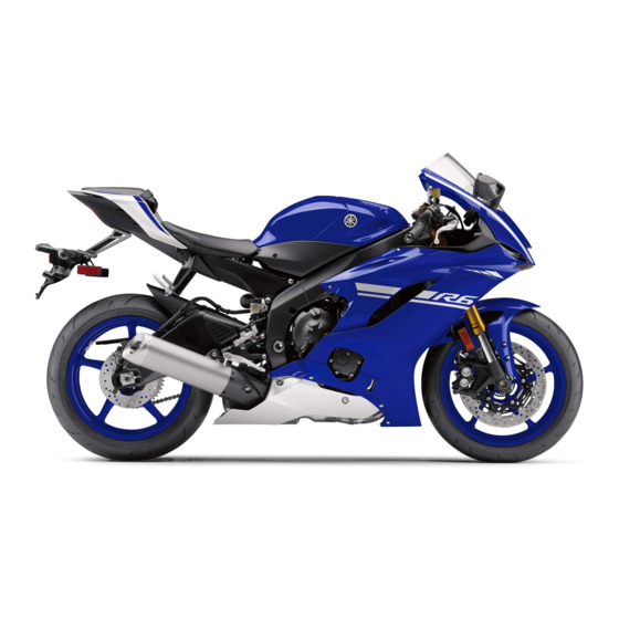
- Page 1 Read this manual carefully before operating this vehicle. OWNER’S MANUAL YZF600W BN6-28199-EA...
- Page 2 EAU81563 Read this manual carefully before operating this vehicle. This manual should stay with this vehicle if it is sold. EAU94831...
- Page 3 EAU10103 Welcome to the Yamaha world of motorcycling! As the owner of the YZF600W, you are benefiting from Yamaha’s vast experience and newest technology regarding the design and manufacture of high-quality products, which have earned Yamaha a reputation for dependability.
- Page 4 Important manual information EAU10134 Particularly important information is distinguished in this manual by the following notations: This is the safety alert symbol. It is used to alert you to potential personal injury hazards. Obey all safety messages that follow this symbol to avoid possible injury or death.
- Page 5 Important manual information EAU10202 YZF600W OWNER’S MANUAL ©2022 by Yamaha Motor Co., Ltd. 1st edition, October 2021 All rights reserved. Any reprinting or unauthorized use without the written permission of Yamaha Motor Co., Ltd. is expressly prohibited. Printed in Japan.
-
Page 6: Table Of Contents
Table of contents Safety information......1-1 Adjusting the shock absorber Air filter element......7-19 assembly........4-23 Checking the engine idling Description ........2-1 EXUP system ........4-26 speed ........7-19 Left view ......... 2-1 Auxiliary DC connector ....4-26 Checking the throttle grip free Right view........ - Page 7 Table of contents Lubricating the swingarm pivots .........7-32 Checking the front fork....7-33 Checking the steering ....7-33 Checking the wheel bearings ..7-34 Battery ...........7-34 Replacing the fuses.......7-35 Supporting the motorcycle....7-37 Troubleshooting ......7-37 Troubleshooting chart ....7-39 Motorcycle care and storage ..8-1 Matte color caution ......8-1 Care ..........8-1 Storage ..........8-3 Specifications........9-1...
-
Page 8: Safety Information
Safety information Never operate a motorcycle with- pears to be very effective in reduc- EAU94530 out proper training or instruction. ing the chance of this type of Take a training course. Beginners accident. Be a Responsible Owner should receive training from a cer- Therefore: As the vehicle’s owner, you are re- tified instructor. - Page 9 Safety information Many accidents involve inexperi- The use of a jacket, heavy boots, • Always signal before turning or enced operators. In fact, many op- changing lanes. Make sure that trousers, gloves, etc., is effective erators who have been involved in other motorists can see you.
- Page 10 To Yamaha accessories, which are avail- instability. avoid the possibility of an accident, use able only from a Yamaha dealer, have Shifting weights can create a sud- extreme caution when adding cargo or been designed, tested, and approved den imbalance.
- Page 11 Never install accessories or carry for Yamaha vehicles. Yamaha is not in passed by large vehicles. a position to test the products that cargo that would impair the per- •...
- Page 12 Safety information The suspension should be com- for tire specifications and for informa- tion on servicing and replacing your pressed somewhat by the tie- tires. downs, if possible, so that the mo- torcycle will not bounce exces- Transporting the Motorcycle sively during transport.
-
Page 13: Description
Description EAU94540 Left view (This image is of the street legal version and is for reference only.) 1. Fuse box 2 (page 7-35) 8. Engine oil filter cartridge (page 7-14) 2. Fuel tank cap (page 4-17) 9. Engine oil drain bolt (page 7-14) 3. -
Page 14: Right View
Description EAU94550 Right view (This image is of the street legal version and is for reference only.) 1,2,3,4 5,6,7 1. Fuse box 1 (page 7-35) 8. Coolant reservoir (page 7-18) 2. Main fuse (page 7-35) 9. Engine oil filler cap (page 7-14) 3. -
Page 15: Controls And Instruments
Description EAU94560 Controls and instruments (This image is of the street legal version and is for reference only.) 1. Clutch lever (page 4-15) 8. Throttle grip (page 7-20) 2. Left handlebar switches (page 4-3) 3. Main switch/steering lock (page 4-2) 4. -
Page 16: Special Features
Special features Mode “B” EAU76422 D-mode (drive mode) Mode “B” offers response that is Make sure you understand each D-mode is an electronically controlled somewhat less sharp compared to drive mode before operating the engine performance system. This mode “STD” for riding situations that drive mode switch. -
Page 17: Traction Control System
Special features EAU79735 Traction control system When the vehicle is turned on, the The traction control system helps traction control system is turned maintain traction when accelerating on on and set to the last used traction slippery surfaces, such as unpaved or control system setting. - Page 18 Special features push down on the traction control ECA16801 EWA18940 NOTICE WARNING system switch to turn the traction Use only the specified tires. (See control system back on. Take extra precaution when chang- page 7-20.) Using different sized ing modes while riding. tires will prevent the traction control Turn the traction control system off to system from controlling tire rotation...
-
Page 19: Quick Shifter
4. Have a Yamaha dealer check the vehicle and turn off the “ ” warning light. The quick shifter operates when travel-... -
Page 20: Instrument And Control Functions
Do not place near magnets. Yamaha dealer to have them re-regis- Do not place near items that tered. 1. Code re-registering key (red bow) 2. Standard keys (black bow) transmit electrical signals. -
Page 21: Main Switch/Steering Lock
Instrument and control functions EAU10474 EAU85050 EAU1068B Main switch/steering lock LOCK All electrical circuits are supplied with The steering is locked and all electrical power and the vehicle lights are turned systems are off. The key can be re- on. The engine can be started. The key moved. -
Page 22: Handlebar Switches
Instrument and control functions Right EAU66057 Handlebar switches If the steering will not lock, try turning Left the handlebars back to the right slight- To unlock the steering 1. Stop/Run/Start switch “ ” 2. Drive mode switch “MODE” 3. Hazard switch “ ”... -
Page 23: Indicator Lights And Warning Lights
10.ABS warning light “ ” 11.Immobilizer system indicator light el warning light will flash repeatedly. If this occurs, have a Yamaha dealer EAU11022 check the vehicle. Turn signal indicator light “ ”... - Page 24 The electrical circuit of the warning vehicle control system. If this occurs, light can be checked by turning the ve- have a Yamaha dealer check the on- hicle on. The warning light should EAU1136A board diagnostic system.
- Page 25 “ON”. The indicator light should Yamaha dealer check the vehicle. do not start the engine, take the come on for a few seconds, and then vehicle and all 3 keys to a Yamaha go off. EAU80372 Shift light dealer to have the standard keys...
-
Page 26: Multi-Function Meter Unit
Instrument and control functions settings while riding can distract the Speedometer EAU3904H Multi-function meter unit operator and increase the risk of an The speedometer shows the vehicle’s accident. traveling speed. multi-function meter unit Tachometer equipped with the following: speedometer ... - Page 27 Instrument and control functions Red zone: 16500 r/min and above 6. Push the “SELECT” button to con- new fast lap within the top 20 will be in- firm the settings and start the serted and the previous F20 will be clock.
- Page 28 Instrument and control functions “L-20” = lap order (most re- Coolant temperature display cent is L1) “F-20” = fastest order (fastest lap time is F1) 1. Lap number/Fastest rank 2. Lap time 1. Coolant temperature display 3. Use the “SELECT” button to scroll This display indicates the temperature the history in ascending order, or of the coolant from 41 °C to 124 °C in...
- Page 29 Instrument and control functions This display shows the selected gear. The neutral position is indicated by “ ” When the vehicle is turned on, the When the coolant temperature and by the neutral indicator light. coolant temperature display is au- display is selected, “C”...
- Page 30 Instrument and control functions Traction control system display Quick shifter icon The multi-function display is equipped with the following: odometer two tripmeters fuel reserve tripmeter instantaneous fuel consumption average fuel consumption total fuel used Navigating the multi-function dis- play 1.
- Page 31 Instrument and control functions The tripmeters show the distance trav- ing kilometers, push the “SELECT” eled since they were last reset. To reset button for one second to switch be- If you do not reset the fuel reserve trip- a tripmeter, push the “RESET” button tween “km/L”...
- Page 32 Instrument and control functions “AVE _ _ _._ MPG”: The average Average fuel consumption When using kilometers, this figure is distance that can be traveled on shown in liters. When using miles, this 1.0 US gal of fuel is shown. figure is shown in gallons.
- Page 33 Instrument and control functions This mode cycles through five control 3. Turn the key to “ON”, and then re- 2. Push the “SELECT” button to con- functions, allowing you to make the fol- lease the “SELECT” button after firm the selected shift light activity. lowing settings in the order listed be- five seconds.
-
Page 34: Clutch Lever
Instrument and control functions engine speed than the activation point, EAU12823 EAU12876 Clutch lever Shift pedal otherwise the shift light will not come 1. Push the “RESET” button to set the deactivation point engine speed. 2. Push the “SELECT” button to con- firm the setting. -
Page 35: Brake Lever
EAU26827 EAU12944 EAU63041 Brake lever Brake pedal The Yamaha ABS (Anti-lock Brake System) features a dual electronic con- trol system, which acts on the front and rear brakes independently. Operate the brakes with ABS as you would conventional brakes. If the ABS... -
Page 36: Fuel Tank Cap
However, special tools are required, so please consult your To close the fuel tank cap Yamaha dealer. With the key still inserted, push down 1. Rear wheel sensor the fuel tank cap. Turn the key 1/4 turn ECA20100 2. -
Page 37: Fuel
Instrument and control functions EAU13222 Fuel The fuel tank cap cannot be closed un- Make sure there is sufficient gasoline in less the key is in the lock. In addition, the tank. the key cannot be removed if the cap is EWA10882 WARNING not properly closed and locked. - Page 38 EAU86072 as well as to the exhaust system. Your Yamaha engine was designed to use unleaded gasoline with a research octane number of 95 or higher. If en- gine knocking or pinging occurs, use a gasoline of a different brand or higher ...
-
Page 39: Fuel Tank Overflow Hose
Instrument and control functions EAU86160 EAU13435 Fuel tank overflow hose Catalytic converter See page 7-14 for canister information. The exhaust system contains catalytic converter(s) to reduce harmful exhaust emissions. EWA10863 WARNING The exhaust system is hot after op- eration. To prevent a fire hazard or burns: ... -
Page 40: Seat
Instrument and control functions EAU94580 EAU79923 Seat Adjusting the front fork To remove the rider seat This model is equipped with adjustable Pull up the corners on the rear of the suspension. The spring preload, re- rider seat, remove the bolts with a bound damping force, and compres- hexagon wrench, and then pull the sion damping force of each leg can be... - Page 41 Instrument and control functions Turn the adjusting nut in direction (b) to decrease the spring preload. When turning the spring preload ad- To set the spring preload, turn the ad- juster in direction (a), it may turn be- juster in direction (b) until it stops, and yond stated specifications,...
-
Page 42: Adjusting The Shock Absorber Assembly
Instrument and control functions tions, however such adjustments EAU79933 Compression damping setting: Adjusting the shock absorber are ineffective and may damage Minimum (soft): assembly the suspension. 23 click(s) in direction (b) Standard: 14 click(s) in direction (b) This model is equipped with adjustable Compression damping force Maximum (hard): suspension. - Page 43 Instrument and control functions Use the special wrench and Spring preload: the extension bar included in Minimum (soft): the tool kit to make the ad- Distance A = 84.9 mm (3.34 in) Standard: justment. Distance A = 89.9 mm (3.54 in) Maximum (hard): Distance A = 92.9 mm (3.66 in) 3.
- Page 44 Instrument and control functions tions, however such adjustments Fast compression damping setting are ineffective and may damage Minimum (soft): the suspension. 5.5 turn(s) in direction (b) Standard: 3 turn(s) in direction (b) Compression damping force Maximum (hard): 0 turn(s) in direction (b) Fast compression damping force Turn the adjusting bolt in direction (a) to increase the compression damping...
-
Page 45: Exup System
EAU15283 EAU70641 EXUP system Auxiliary DC connector are ineffective and may damage This model is equipped with Yamaha’s This vehicle is equipped with an auxil- the suspension. EXUP (EXhaust Ultimate Power valve) iary DC connector. Consult your EWA10222 system. -
Page 46: Sidestand
EAU15306 EAU57952 Sidestand Ignition circuit cut-off system Yamaha dealer repair it if it does not The sidestand is located on the left This system prevents in-gear engine function properly. side of the frame. Raise the sidestand... - Page 47 The neutral switch may not be working. 6. Move the sidestand up. The motorcycle should not be ridden until 7. Pull the clutch lever. checked by a Yamaha dealer. 8. Shift transmission into gear. 9. Move the sidestand down. Does the engine stall? The sidestand switch may not be working.
-
Page 48: For Your Safety - Pre-Operation Checks
• If necessary, add recommended coolant to specified level. 7-18 Coolant • Check cooling system for leakage. • Check operation. • If soft or spongy, have Yamaha dealer bleed hydraulic system. • Check brake pads for wear. Front brake • Replace if necessary. 7-25, 7-26 •... - Page 49 • Make sure that operation is smooth. • Check throttle grip free play. 7-20, 7-30 Throttle grip • If necessary, have Yamaha dealer adjust throttle grip free play and lubricate ca- ble and grip housing. • Make sure that operation is smooth. Control cables 7-30 •...
- Page 50 • Tighten if necessary. Instruments, lights, signals • Check operation. — and switches • Correct if necessary. • Check operation of ignition circuit cut-off system. Sidestand switch 4-27 • If system is not working correctly, have Yamaha dealer check vehicle.
-
Page 51: Operation And Important Riding Points
ECA10311 NOTICE there is a control or function you do not between 0 and 1600 km (1000 mi). For understand, ask your Yamaha dealer. this reason, you should read the fol- Keep the engine speed out of EWA10272 lowing material carefully. -
Page 52: Starting The Engine
This model is equipped with: the transmission is in the neutral Yamaha dealer check the vehicle. a lean angle sensor. This sensor position or stops the engine in case of a turn- ... -
Page 53: Shifting
Operation and important riding points 3. Open the throttle gradually, and at EAU77403 ECA22523 Shifting NOTICE the same time, release the clutch When shifting, press the shift lever slowly. pedal firmly until you feel the 4. After starting out, close the throt- gear shift is complete. -
Page 54: Parking
Operation and important riding points 4. Once motorcycle EAU17214 Parking stopped, the transmission can be When parking, stop the engine, and shifted into the neutral position. then remove the key from the main The neutral indicator light should switch. come on and then the clutch lever EWA10312 can be released. -
Page 55: Periodic Maintenance And Adjustment
To avoid possible burns, let tivities incorrectly may increase brake components cool before your risk of injury or death during touching them. service or while using the vehicle. If you are not familiar with vehicle ser- vice, have a Yamaha dealer perform service. -
Page 56: Tool Kit
However, a torque wrench and other tools are necessary to perform certain maintenance work correctly. If you do not have the tools or experi- ence required for a particular job, have your Yamaha dealer perform it for you. -
Page 57: Periodic Maintenance Charts
EAU71033 Periodic maintenance charts Items marked with an asterisk should be performed by your Yamaha dealer because these items require special tools, data, and technical skills. From 50000 km (30000 mi), repeat the maintenance intervals starting from 10000 km (6000 mi). - Page 58 Periodic maintenance and adjustment ODOMETER READING ANNUAL ITEM CHECK OR MAINTENANCE JOB 1000 km 10000 km 20000 km 30000 km 40000 km CHECK (600 mi) (6000 mi) (12000 mi) (18000 mi) (24000 mi) • Check control system for dam- Evaporative emis- √...
-
Page 59: General Maintenance And Lubrication Chart
• Perform dynamic inspection us- Diagnostic system √ √ √ √ √ √ ing Yamaha diagnostic tool. check • Check the error codes. 2 * Air filter element • Replace. Every 40000 km (24000 mi) • Check operation. √ √... - Page 60 Periodic maintenance and adjustment ODOMETER READING ANNUAL ITEM CHECK OR MAINTENANCE JOB 1000 km 10000 km 20000 km 30000 km 40000 km CHECK (600 mi) (6000 mi) (12000 mi) (18000 mi) (24000 mi) • Check operation and for exces- √ √...
- Page 61 Periodic maintenance and adjustment ODOMETER READING ANNUAL ITEM CHECK OR MAINTENANCE JOB 1000 km 10000 km 20000 km 30000 km 40000 km CHECK (600 mi) (6000 mi) (12000 mi) (18000 mi) (24000 mi) • Check operation and replace if √ √...
- Page 62 Periodic maintenance and adjustment ODOMETER READING ANNUAL ITEM CHECK OR MAINTENANCE JOB 1000 km 10000 km 20000 km 30000 km 40000 km CHECK (600 mi) (6000 mi) (12000 mi) (18000 mi) (24000 mi) • Check operation and free play. • Adjust the throttle cable free play Throttle grip hous- √...
-
Page 63: Removing And Installing Cowlings
Periodic maintenance and adjustment EAU18782 Removing and installing cowl- ings The cowlings shown need to be re- moved to perform some of the mainte- nance jobs described in this chapter. Refer to this section each time a cowl- ing needs to be removed and installed. 1. - Page 64 Periodic maintenance and adjustment 1. Quick fastener 1. Cowling A 1. Cowling A 2. Slide the cowling as shown. 3. Install the bolts, quick fasteners, To install the cowling and quick fastener screw. 1. Slide the cowling rearward, and then fit the upper projections into the slots.
- Page 65 Periodic maintenance and adjustment 1. Cowling B 1. Cowling C 1. Quick fastener 2. Bolt 2. Bolt 2. Slide the cowling as shown. 3. Quick fastener screw To install the cowling 1. Place cowling B in its original po- sition, and then install the bolts. 2.
- Page 66 Periodic maintenance and adjustment 1. Cowling C 1. Cowling C 1. Cowling D 2. Bolt 3. Install the bolts, quick fastener, To install the cowling and quick fastener screw. To install the cowling 1. Fit the upper projections into the 1.
-
Page 67: Checking The Spark Plugs
1/2 turn past finger tight. However, the Yamaha dealer. Since heat and depos- with a wire thickness gauge and, if spark plug should be tightened to the its will cause any spark plug to slowly necessary, adjusted to specification. -
Page 68: Canister
Periodic maintenance and adjustment EAU36113 EAU3899J Canister Engine oil and oil filter car- tridge The engine oil level should be checked before each ride. In addition, the oil must be changed and the oil filter car- tridge replaced at the intervals speci- fied in the periodic maintenance and lubrication chart. - Page 69 Periodic maintenance and adjustment 4. Place an oil pan under the engine to collect the used oil. 5. Remove the engine oil filler cap, the engine oil drain bolt and its gasket to drain the oil from the crankcase. 1. Engine oil filler cap 1.
- Page 70 An oil filter wrench is available at a to shift up or down. [ECA24140] Yamaha dealer. 9. Apply a thin coat of clean engine oil to the O-ring of the new oil filter cartridge.
-
Page 71: Why Yamalube
Yamaha dealer check mix any chemical additives. Do the 1960’s helps make Yamalube the the vehicle. -
Page 72: Coolant
2. Maximum level mark soft tap water instead. Do not 3. Minimum level mark If genuine Yamaha coolant is not avail- use hard water or salt water 3. If the coolant is at or below the since it is harmful to the engine. -
Page 73: Air Filter Element
The coolant must be changed at the in- maintenance and lubrication chart. necessary, have it corrected by a tervals specified in the periodic main- Have a Yamaha dealer replace the air Yamaha dealer. tenance and lubrication chart. Have a filter element. -
Page 74: Checking The Throttle Grip Free Play
3.0–5.0 mm (0.12–0.20 in) improper tire air pressure may Periodically check the throttle grip free cause severe injury or death play and, if necessary, have a Yamaha from loss of control. The tire air pressure must be dealer adjust it. - Page 75 “broken wall is cracked, have a Yamaha dealer in” for it to develop its optimal replace the tire immediately. characteristics.
- Page 76 1. Tire air valve BRIDGESTONE/BATTLAX ed below are approved for this model HYPERSPORT S21R 2. Tire air valve core by Yamaha. FRONT and REAR: 3. Tire air valve cap with seal Tire air valve: This model is equipped with tubeless...
-
Page 77: Cast Wheels
The tires must be warmed up ride. If any damage is found, have before a high-speed run. a Yamaha dealer replace the Always adjust the tire air pres- wheel. Do not attempt even the sure according to the operating smallest repair to the wheel. -
Page 78: Checking The Brake Lever Free Play
1. No brake lever free play There should be no free play at the brake lever end. If there is free play, have a Yamaha dealer inspect the brake system. EWA14212 WARNING A soft or spongy feeling in the brake lever can indicate the presence of 1. -
Page 79: Brake Light Switches
EAU36891 Front brake pads Yamaha dealer. 1. Brake pad wear indicator Each front brake pad is provided with wear indicators, which allows you to check the brake pad wear without hav- ing to disassemble the brake. -
Page 80: Checking The Brake Fluid Level
Rear brake EAU40262 Checking the brake fluid level Yamaha dealer replace the brake pads Before riding, check that the brake fluid as a set. is above the minimum level mark. Check the brake fluid level with the top... -
Page 81: Changing The Brake Fluid
EAU22734 Changing the brake fluid id; otherwise, the rubber seals Yamaha dealer check the cause before Have a Yamaha dealer change the may deteriorate, causing leak- further riding. brake fluid every 2 years. In addition, age. -
Page 82: Drive Chain Slack
To adjust the drive chain slack 2. To tighten the drive chain, turn the neutral position. Consult a Yamaha dealer before ad- drive chain slack adjusting bolt on 3. Measure the drive chain slack as justing the drive chain slack. -
Page 83: Cleaning And Lubricating The Drive Chain
Periodic maintenance and adjustment 4. Make sure that the drive chain EAU23027 Cleaning and lubricating the pullers are in the same position, drive chain the drive chain slack is correct, The drive chain must be cleaned and drive chain moves lubricated at the intervals specified in smoothly. -
Page 84: Checking And Lubricating The Cables
Yamaha dealer at the intervals cated if necessary. If a cable is specified in the periodic maintenance damaged or does not move smoothly, chart. -
Page 85: Checking And Lubricating The Brake And Shift Pedals
Periodic maintenance and adjustment EAU44276 EAU23144 Recommended lubricant: Checking and lubricating the Checking and lubricating the Lithium-soap-based grease brake and shift pedals brake and clutch levers The operation of the brake and shift The operation of the brake and clutch pedals should be checked before each levers should be checked before each ride, and the pedal pivots should be lu-... -
Page 86: Checking And Lubricating The Sidestand
The operation of the sidestand should The swingarm pivots must be lubricat- be checked before each ride, and the ed by a Yamaha dealer at the intervals sidestand pivot and metal-to-metal specified in the periodic maintenance contact surfaces should be lubricated and lubrication chart. -
Page 87: Checking The Front Fork
[EWA10752] tion. WARNING! To avoid injury, 2. Hold the lower ends of the front have a Yamaha dealer check or re- securely support the vehicle so fork legs and try to move them for- pair it. -
Page 88: Checking The Wheel Bearings
EWA10761 WARNING To charge the battery Electrolyte is poisonous and Have a Yamaha dealer charge the bat- dangerous since it contains sul- tery as soon as possible if it seems to furic acid, which causes severe have discharged. Keep in mind that the... -
Page 89: Replacing The Fuses
Periodic maintenance and adjustment battery tends to discharge more quick- nect the positive lead before EAU94641 Replacing the fuses ly if the vehicle is equipped with op- connecting the negative lead. The main fuse, the ABS motor fuse, tional electrical accessories. [ECA16842] and fuse box 1 are located under the ECA16522... - Page 90 Periodic maintenance and adjustment Specified fuses: Main fuse: 50.0 A Terminal fuse 1: 2.0 A Fuel injection system fuse: 15.0 A ABS motor fuse: 30.0 A ABS ECU fuse: 7.5 A 1. Fuse box 1 1. Fuse box 2 ABS solenoid fuse: 2.
-
Page 91: Supporting The Motorcycle
1. Maintenance stand (example) self. However, should your motorcycle Since this model is not equipped with a require any repair, take it to a Yamaha centerstand, use maintenance stands dealer, whose skilled technicians have when removing the front or rear wheel... - Page 92 Periodic maintenance and adjustment heaters or furnaces. Gasoline or gasoline vapors can ignite or ex- plode, causing severe injury or prop- erty damage. 7-38...
-
Page 93: Troubleshooting Chart
Remove the spark plug and check the electrodes. The engine does not start. Have a Yamaha dealer check the vehicle. Check the compression. 4. Compression The engine does not start. There is compression. - Page 94 Start the engine. If the engine overheats again, have a The coolant level Yamaha dealer check and repair the cooling system. is OK. If coolant is not available, tap water can be temporarily used instead, provided that it is changed to the recommended cool- ant as soon as possible.
-
Page 95: Motorcycle Care And Storage
Be performance and extend the useful life high-pressure washers sure to consult a Yamaha dealer for of many components. Washing, clean- steam-jet cleaners. Excessive ing, and polishing will also give you a advice on what products to use be-... - Page 96 Motorcycle care and storage chemicals such as, solvents, Washing plastic may scratch the wind- gasoline, rust removers, brake 1. Rinse off any degreaser and spray shield, so be sure to test all fluid, or antifreeze, etc. down the vehicle with a garden cleaning products before gen- hose.
-
Page 97: Storage
Motorcycle care and storage Do not use abrasive polishing will become slippery, which EAU83472 Storage could cause loss of control. compounds as they will wear Always store the vehicle in a cool, dry Thoroughly clean the surfaces away the paint. place. - Page 98 Motorcycle care and storage 1. Make all necessary repairs and b. Pour a teaspoonful of engine wheels a little once a month in or- perform any outstanding mainte- oil into the spark plug bore. der to prevent the tires from be- nance.
-
Page 99: Specifications
Specifications Dimensions: Fuel injection: Starting system: Electric starter Overall length: Throttle body: Engine oil: 1990 mm (78.3 in) ID mark: Overall width: Recommended brand: BN64 695 mm (27.4 in) Drivetrain: Overall height: Gear ratio: 1150 mm (45.3 in) 1st: Seat height: 2.583 (31/12) 850 mm (33.5 in) 2nd:... - Page 100 Specifications Manufacturer/model: DUNLOP/SPORTMAX D214 Manufacturer/model: BRIDGESTONE/BATTLAX HYPERSPORT S21R Loading: Maximum load: 190 kg (419 lb) (Total weight of rider, cargo and accessories) Front brake: Type: Hydraulic dual disc brake Rear brake: Type: Hydraulic single disc brake Front suspension: Type: Telescopic fork Rear suspension: Type: Swingarm (link suspension)
-
Page 101: Consumer Information
These identification numbers are needed when registering the vehicle with the authorities in your area and when ordering spare parts from a Yamaha dealer. VEHICLE IDENTIFICATION NUMBER: 1. Vehicle identification number 1. Engine serial number The vehicle identification number is The engine serial number is stamped stamped into the steering head pipe. -
Page 102: Diagnostic Connector
The diagnostic connector is located as ed data shown. This data will be uploaded only when a special Yamaha diagnostic tool is at- tached to the vehicle, such as when maintenance checks or service proce- dures are performed. Vehicle data uploaded will be handled appropriately according to the follow- ing Privacy Policy. - Page 103 Consumer information Yamaha will not disclose this data to a third party except in the following cas- es. In addition, Yamaha may provide vehicle data to a contractor in order to outsource services related to the han- dling of vehicle data. Even in this case,...
-
Page 104: Index
Index Multi-function meter unit......4-7 ABS............4-16 Engine break-in ........6-1 ABS warning light ........4-5 Engine idling speed, checking ..... 7-19 Neutral indicator light......4-4 Air filter element ........7-19 Engine oil and oil filter cartridge ... 7-14 Auxiliary DC connector ......4-26 Engine overheating....... 7-40 Oil level warning light ......4-4 Engine serial number...... - Page 105 Index Tool kit............ 7-2 Traction control system......3-2 Traction control system indicator light ... 4-6 Traction control system switch ....4-4 Troubleshooting........7-37 Troubleshooting chart ......7-39 Turn signal indicator light ....... 4-4 Valve clearance ........7-20 Vehicle identification number ....10-1 Wheel bearings, checking ....
- Page 108 Original instructions PRINTED IN JAPAN 2021.11-0.3×1 CR (E)
Need help?
Do you have a question about the R6 YZF600W and is the answer not in the manual?
Questions and answers