Table of Contents
Advertisement
CONTENTS
SAFETY CONSIDERATIONS . . . . . . . . . . . . . . . . . . . . . . 1
INSTALLATION . . . . . . . . . . . . . . . . . . . . . . . . . . . . . . . . .1-11
Step 1 - Rig and Place the Unit. . . . . . . . . . . . . . . . . . 1
• RIGGING
• PLACING UNIT
Step 2 - Check Compressor Mounting . . . . . . . . . . 3
Connections . . . . . . . . . . . . . . . . . . . . . . . . . . . . . . . . . . . . 3
OPERATION
Step 4 - Make Electrical Connections . . . . . . . . . . . 7
Step 5 - Install Accessories . . . . . . . . . . . . . . . . . . . . 11
• ELECTRICAL
Step 6 - Refrigerant Circuit. . . . . . . . . . . . . . . . . . . . . 11
• DEHYDRATION
SAFETY CONSIDERATIONS
Installing, starting up, and servicing air-conditioning equip-
ment can be hazardous due to system pressures, electrical com-
ponents, and equipment location (roofs, elevated structures,
etc).
Only trained, qualified installers and service mechanics
should install, start up, and service this equipment (Fig. 1).
Untrained personnel can perform basic maintenance func-
tions such as cleaning coils. All other operations should be per-
formed by trained service personnel.
When working on the equipment, observe precautions in the
literature and on tags, stickers, and labels attached to the
equipment.
• Follow all safety codes.
• Wear safety glasses and work gloves.
• Keep quenching cloth and fire extinguisher nearby when
brazing.
• Use care in handling, rigging, and setting bulky
equipment.
• See Tables 1A and 1B for Physical Data.
ELECTRIC SHOCK HAZARD
Open all remote disconnects before servicing
this equipment.
Manufacturer reserves the right to discontinue, or change at any time, specifications or designs without notice and without incurring obligations.
PC 903
Book 2
Tab
5c
Installation Instructions
Page
Catalog No. 563-068
Printed in U.S.A.
Reciprocating Liquid Chillers
with ComfortLink™ Controls
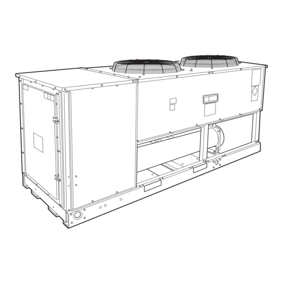
Fig. 1 - Model 30GTN (020 Shown)
INSTALLATION
Step 1 - Rig and Place the Unit
RIGGING - Preferred method is with spreader bars from
above the unit. Use 2-in. (50 mm) OD pipe or hooks in lifting
holes. Rig with 4 cables and spreader bars. All panels must be
in place when rigging. See rigging label on unit for details con-
cerning shipping weights, distance between lifting holes, center
of gravity, and spreader bar dimensions. See Fig. 2.
If overhead rigging is not possible, place chiller on skid or
pad for rolling or dragging. When rolling, use a minimum of
3 rollers. When dragging, pull the pad. Do not apply force to
the unit. When in final position, raise from above to lift unit off
pad.
All panels must be in place when rigging.
PLACING UNIT - There must be at least 4 ft (1.2 m) for
service and for unrestricted airflow on all sides of unit, and a
minimum of 8 ft (2.4 m) clear air space above unit. Provide
ample room for servicing cooler. For cooler removal see clear-
ance requirements in Fig. 3-5. For multiple units, allow 8 ft
(2.4 m) separation between units for airflow and service.
If unit is to be used in an area with high solar radiation,
mounted position should be such that control box is not ex-
posed to direct solar radiation. Exposure to direct solar radia-
tion could affect the temperature switch controlling cooler
heaters. See Table 2.
Form 30GTN-10SI
Pg 1
30GTN015-035
50/60 Hz
1-00
Replaces: New
Advertisement
Table of Contents

Subscribe to Our Youtube Channel
Related Manuals for Carrier 30GTN015-035


Summary of Contents for Carrier 30GTN015-035
-
Page 1: Table Of Contents
Exposure to direct solar radia- tion could affect the temperature switch controlling cooler heaters. See Table 2. Printed in U.S.A. Form 30GTN-10SI 30GTN015-035 50/60 Hz Pg 1 1-00 Replaces: New... - Page 2 Net Water Volume, gal. (L) Maximum Design Working Pressure psig (kPa) WATER CONNECTIONS, in. Inlet and Outlet Drain *See Oil Charge section for Carrier-approved oil. UNIT 30GTN COMPRESSOR No..Type No. Cyls (ea)...Speed, Rpm (r/s) Capacity Steps Oil Charge*, Pt (L) REFRIGERANT CHG, R-22 →...
-
Page 3: Mounting Unit
LIFTING CENTER OF GRAVITY MAXIMUM HOLES UNIT SHIP WT “B” “A” 30GTN 1876 94.0 2388 48.0 1219 23.0 583 49.5 1256 2031 94.0 2388 47.5 1207 23.0 583 49.5 1256 2415 1095 94.0 2388 51.0 1295 34.5 876 73.5 1867 2606 1182 94.0 2388 51.0 1295 34.5 876 73.5 1867 3365 1526... - Page 4 NOTES: 1. There must be minimum 8 ft (2.4 m) clear air space above unit. 2. Dimensions in [ ] are in millimeters. 3. The approximate operating weight of the unit is: 60 Hz UNIT 30GTN015 1640 30GTN015C 1732 30GTN020 1821 30GTN020C 1945...
- Page 5 NOTES: 1. There must be minimum 8 ft (2.4 m) clear air space above unit. 2. Dimensions in [ ] are in millimeters. 3. The approximate operating weight of the unit is: 60 Hz UNIT 30GTN025 2170 30GTN025 30GTN025C 2324 1054 30GTN025C 30GTN030...
- Page 6 NOTES: 1. There must be minimum 8 ft (2.4 m) clear air space above unit. 2. Dimensions in [ ] are in millimeters. 3. The approximate operating weight of the unit is: 60 Hz UNIT 30GTN035 2965 1345 30GTN035C 3273 1485 LEGEND —...
-
Page 7: Step 4 - Make Electrical Connections
Tables 3A and 3B. IMPORTANT: Operating unit on improper supply volt- age or with excessive phase imbalance constitutes abuse and may affect Carrier warranty. POWER WIRING — All power wiring must comply with ap- plicable local and national codes. Install field-supplied branch circuit fused disconnect(s) per NEC (National Electrical Code, U.S.A.) of a type that can be locked OFF or ON. - Page 8 Table 3A — Electrical Data — Standard Unit UNIT SIZE Supplied* Voltage 30GTN V-Hz (3 Ph) 208/230-60 460-60 575-60 380-60 380/415-50 208/230-60 460-60 575-60 380-60 380/415-50 208/230-60 460-60 575-60 380-60 380/415-50 208/230-60 460-60 575-60 380-60 380/415-50 208/230-60 460-60 575-60 380-60 See Legend and Notes on page 9.
- Page 9 Table 3B — Electrical Data — Unit with Factory-Installed Motormaster® I Control UNIT SIZE Supplied* Voltage 30GTN V-Hz (3 Ph) 208/230-60 460-60 575-60 380-60 380/415-50 208/230-60 460-60 575-60 380-60 380/415-50 208/230-60 460-60 575-60 380-60 380/415-50 208/230-60 460-60 575-60 380-60 380/415-50 208/230-60 460-60 575-60...
- Page 10 LEGEND — Compressor Contactor — Circuit Breaker — Carrier Comfort Network CWFS — Chilled Water Flow Switch — Chilled Water Pump CWPI — Chilled Water Pump Interlock — Fan Contactor — Ground Current Sensor — Local Equipment Network — Main Base Board —...
-
Page 11: Step 5 - Install Accessories
After leaks are repaired, system must be evacuated and dehydrated prior to recharging with refrigerant. DEHYDRATION — Refer to Carrier Standard Service Tech- niques Manual, Chapter 1, Refrigerants, Sections 6 and 7 for details. Do not use compressor to evacuate system. - Page 12 Copyright 2000 Carrier Corporation Manufacturer reserves the right to discontinue, or change at any time, specifications or designs without notice and without incurring obligations. Book 2 PC 903 Catalog No. 563-068 Printed in U.S.A. Form 30GTN-10SI Pg 12 1201 1-00...
Need help?
Do you have a question about the 30GTN015-035 and is the answer not in the manual?
Questions and answers