Tait TD9300 Installation And Configuration Manual
Data terminal
Hide thumbs
Also See for TD9300:
- Installation manual (34 pages) ,
- Installation and configuration manual (71 pages)

Related Manuals for Tait TD9300

Summary of Contents for Tait TD9300
- Page 1 TD9300 Data Terminal Installation and Configuration Manual MNE-00003-08 · Issue 8· September 2018...
- Page 2 Environmental Responsibilities Tait International Limited. Tait International Limited is an The word TAIT and the TAIT logo are trademarks of environmentally responsible company Tait International Limited. which supports waste minimization, material recovery and restrictions in the All trade names referenced are the service mark, use of hazardous materials.
-
Page 3: Table Of Contents
3.2 Connecting to the TD9300 using the Ethernet Port ......28 3.3 Connecting to the TD9300 Web Interface ....... 31 TD9300 Installation and Configuration Manual ©... - Page 4 Configuration ............35 4.1 Configuring the Ethernet Port of the TD9300 ......35 4.1.1 Configuring IP Settings using the Web UI.
- Page 5 Tait Software License Agreement ........
-
Page 6: Preface
TD9300 in a TN9300 DMR trunked network. Document Conventions The TD9300 data terminal has a web interface with an accordion menu on the left side of the screen. As an example, “Monitor > Dashboard” means click Monitor in the top-level menu, then click Dashboard in the expanded Monitor menu tree to display its page. -
Page 7: Publication Record
Updated images throughout. Updated ‘isolated ports’ and ‘RF connector’ in “Safety and Regulatory Information” on page TD9300 model terms: non-isolated, isolated v1 and isolated v2 now included throughout. Added sub-section “Fuse and Wiring Requirements” on page 21 “Connections” chapter has been replaced with “System Connections”... -
Page 8: Safety And Regulatory Information
USA Federal Communications Commission OET bulletin 65 (47CFR 1.1310) IEEE C95.1 2005: Standard for Safety Levels with Respect to Human Exposure to Radio Frequency Electromagnetic Fields, 3kHz to 300GHz Safety and Regulatory Information TD9300 Installation and Configuration Manual © Tait International Limited September 2018... -
Page 9: Equipment Safety
Antenna Load Transmitting into a low VSWR will maximize the power delivered to the antenna. Notice Do not disconnect the antenna from the TD9300 while it is transmitting. Load transients (switching or removing the load) can damage the transmitter. - Page 10 ESD S20.20-1999 or BS EN 100015-4 1994. Figure 2.1 Typical antistatic bench set-up common point ground (building ground or mains ground) dissipative rubber bench mat conductive wrist strap Safety and Regulatory Information TD9300 Installation and Configuration Manual © Tait International Limited September 2018...
-
Page 11: Environmental Conditions
(–30°C to +60°C) ambient temperature. Humidity The humidity should not exceed 95% relative humidity through the specified operating temperature range. Dust and Dirt The TD9300 has the following ingress protection ratings: IP40 ■ IP41 with the front panel connectors facing down ■... -
Page 12: Regulatory Information
(1) l'appareil ne doit pas produire de brouillage, et (2) l'utilisateur de l'appareil doit accepter tout brouillage radioélectrique subi, même si le brouillage est susceptible d'en compromettre le fonctionnement. Safety and Regulatory Information TD9300 Installation and Configuration Manual © Tait International Limited September 2018... - Page 13 Unauthorized Modifications Any modifications you make to this equipment which are not authorized by Tait may invalidate your compliance authority’s approval to operate the equipment. The manufacturer is not responsible for any radio or TV interference caused by unauthorized modifications to this equipment. Such modifications could void the user’s authority to operate the equipment.
- Page 14 Safety and Regulatory Information TD9300 Installation and Configuration Manual © Tait International Limited September 2018...
-
Page 15: Introduction
Introduction The TD9300 data terminal is an element of the Tait solution for grid automation on electricity distribution networks. It uses its RF capability to connect over the Tait DMR Tier 3 trunked network to exchange DMR control channel and packet data messages with the Tait SCADA Gateway. -
Page 16: Td9300 Models
TD9300 Models The TD9300 is available in the following models: Model DC Input Connector Labeling T04-00002-xCxx (non-isolated) Signal ports and DC input not isolated T04-00002-xAxx (isolated v1) with external DC/DC Converter Signal ports only isolated T04-00002-xDxx (isolated v2) Signal ports and DC input isolated With all models, the RF port is not isolated. -
Page 17: Frequency Bands
The TD9300 is registered on the DMR network From TD9300 v1.06 onwards, LEDs 1 and 2 will flash simultaneously at 500ms intervals while the TD9300 is in radio programming mode when selected using the TD9300 web user interface. Ethernet link... -
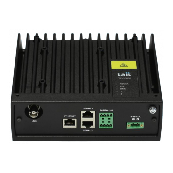
Page 18: Connectors
A matching cable connector is supplied with the TD9300. Ground M4 chassis ground connector. An M4x10mm screw and washers are supplied with the TD9300. “Specifications” on page 63 for more information on these signals. -
Page 19: Pinouts
RS232 transmit data out from TD9300 (or RS485 -) RS232 receive data in to TD9300 (or RS485 +) clear to send out from TD9300 request to send in to TD9300 Digital Input/Output External View... -
Page 20: System Connections
Figure 1.1 shows examples of the basic system connections when a TD9300 is used with an RTU or IED. Notice With the exception of the RF cable, all cables connected to the TD9300 must be less than 10ft (3m) long. -
Page 21: Fuse And Wiring Requirements
1.4.4 Fuse and Wiring Requirements The TD9300 must be connected to the DC power supply via a fuse with a maximum rating of: for 12V operation at 25W RF Power: 10A/250VP (Littlefuse Type 314 ■ or equivalent) for 24V operation at 25W RF Power: 5A/250VP (Littlefuse Type 314 or ■... -
Page 22: Tait Product Numbering
Tait Product Numbering 1.6.1 Product Codes For the TD9300, the Tait product codes follow the ‘T04-00002-XXXX’ format, where: ‘T04’ identifies the code for a data terminal radio ■ ‘00002’ identifies the product as a TD9300 ■ ‘XXXX’ (alphabetic) identifies the configuration ■... -
Page 23: Installation
TD9300 without bending, but also rigid enough to prevent excessive vibration of the TD9300. If access to the rear of the TD9300 is restricted when it is installed, it may be difficult to release the latch to remove the TD9300 at a later date. - Page 24 Figure 2.1 DIN rail mounting Recommended mounting method 35mm DIN rail M3 Taptite screw (x4) maximum torque 15lbf·in (1.7N·m) Mounting Removal TD9300 Installation and Configuration Manual © Tait International Limited September 2018...
-
Page 25: Flat Mounting
Flat Mounting The TD9300 can also be mounted directly on a flat surface using the optional mounting brackets (mounting kit T04-00088-0001, refer to Figure 2.2). Four holes are provided on the bottom of the chassis for securing these brackets with the M4x12 Taptite screws supplied with the TD9300. -
Page 26: Taptite Screws
(x10) 6.5 in (165 mm) Taptite Screws The mounting holes provided in the chassis of the TD9300 (as shown in Figure 2.3) are designed for use with trilobular thread-rolling screws, such as Taptite. Tait recommends using the Taptite screws provided with the equipment to mount the TD9300. -
Page 27: Connecting To The Td9300
TD9300 LMR configuration. If connecting through the Ethernet port and the TD9300 IP address isn’t known, you can connect to the TD9300 using a serial connection to obtain the IP address. Connecting to the TD9300 using a... -
Page 28: Connecting To The Td9300 Using The Ethernet Port
■ ■ Mask:255.255.255.240 The IP addresses of the TD9300 and the PC need to be in the same sub- net but cannot be the same. You can use a subnet mask calculator to establish the range. Enter exit to disconnect from the session. Then close the terminal window. - Page 29 Configuring the PC IP Address a similar way. Open Control Panel > Network and Internet > Network and Sharing Center. Select Change Adapter Settings. Open Local Area Connection. Click Properties. TD9300 Installation and Configuration Manual © Tait International Limited September 2018...
- Page 30 Click Internet Protocol Version 4 (TCP/IPv4), then click Properties. The IP addresses of the TD9300 and the PC need to be in the same sub- net but cannot be the same. You can use a subnet mask calculator to establish the range.
-
Page 31: Connecting To The Td9300 Web Interface
Files: Allows you to delete, upload and install firmware files. It also ■ allows you to download or delete alarm and log files. Before first connecting to the TD9300 using the web browser or an SSH application, you need to configure the IP address of the PC (see “Con- figuring the PC IP Address”... - Page 32 TD9300 web interface components. The web interface will still function, but some features may be missing or operate unexpectedly. The TD9300 needs to receive a local firmware upgrade to the same version as shown in the (app) reference, or a later version.
-
Page 33: Enabling And Disabling Communication To The Rf Board
Click ‘Enter program mode’ at the bottom of the page Click ‘Exit program mode’. Disabling Communication To log out, click ‘logout’ at the top-right corner of the web interface. TD9300 Installation and Configuration Manual © Tait International Limited September 2018... -
Page 34: Enabling And Disabling Communication Using Portmonitor
Make sure you are logged in as a root user using the su command and the root access password K1w1k1w1. From TD9300 firmware version 1.04, you can also use the sudo com- mand in front of commands that require root-level access. -
Page 35: Configuration
Configuration Configuring the Ethernet Port of the TD9300 The network configuration of the Ethernet port can be edited using the TD9300 web UI or via connection to the SERIAL 2 port, or SSH over Ethernet. 4.1.1 Configuring IP Settings using the Web UI... -
Page 36: Address And Protocol Configuration Settings
Example: ping 192.168.1.1 Address and Protocol Configuration Settings Addressing and protocol settings can be configured through the TD9300 web UI. This section outlines the process for configuring addressing and protocol settings, and also describes the parameters that can be configured. -
Page 37: Programming The Rf Board
“Enabling and Disabling Communication to the RF Board” on page Use the TM9300/TP9300 programming application to read the configuration file from the RF board. The TD9300 will appear as a TM9300 in the programming application. Configure the following fields: Feature Form... - Page 38 TD9300 Installation and Configuration Manual © Tait International Limited September 2018...
-
Page 39: Web Interface Reference
Web Interface Reference Monitor > Dashboard TD9300 Installation and Configuration Manual © Tait International Limited September 2018... -
Page 40: General
There has been no data activity with the The RTU indicator on the TD9300 top panel mirrors this indicator, where: On = Data has been sent to an RTU connected to the TD9300, and the ■ TD9300 has received a response from the RTU. -
Page 41: Terminal State
■ 5.1.3 Terminal state The voltage at the TD9300 DC input, the indicator shows red if the DC Supply voltage input is out of the 9-36V input range. For v1 isolated TD9300s, which require a 24V input, the valid input is still shown as 9-36V. -
Page 42: Dmr Traffic
Status messages sent the SCADA Gateway. If Outgoing Data Call is enabled, the TD9300 will generate a data call directly to the SCADA Gateway instead of sending a callback status message. Count of the number of callback status messages which failed to reach the... -
Page 43: Ip Traffic
Count of SCADA messages (and total bytes) sent from the TD9300 to a Transmitted SCADA messages serial or Ethernet connected RTU, as defined by the configured SCADA protocol. 5.1.7 IP Traffic Count of the IP packets (and total bytes) received on the TD9300 Ethernet Received packets interface, not including proxied SCADA traffic. -
Page 44: Configure > Terminal
Address of the Dispatcher Interface Protocol connection in MPT1327 DIP address format (and DMR format) that the TD9300 uses to connect to the SCADA Gateway, this should be the same address as defined in the SCADA Gateway Division that the radio address of this TD9300 belongs to. -
Page 45: Encryption
SCADA gateway. 5.2.3 Encryption If the TD9300 contains an encryption license, or has v1.12 or later of the Password Tait GridLink application, entering a password will cause all over-the-air communications with the SCADA Gateway to be encrypted. The SCADA Gateway must have the same password set in the config- uration of the same terminal. -
Page 46: Dhcp
For Connection = Serial, the following fields apply: The serial speed in bits per second of the TD9300 Serial 1 port, needs to be Baud set the same as the RTU serial port. Specify whether an odd, even or no parity bit is used in the serial Parity communication, needs to be set the same as the RTU serial port. -
Page 47: Ssh
Alternatively, upon successful loading of an existing private key file, the public key will be displayed. Copy the entire public key contents starting from ssh-rsa until end of the key and paste it in SSH Public key entry box in the TD9300 web interface. TD9300 Installation and Configuration Manual... - Page 48 To establish a SSH session with the TD9300 with public key authentication enabled: Run PuTTY and enter the IP address of the TD9300 in the Session window and select Connection Type SSH. Navigate to the PuTTY Connection > SSH > Auth page and click Browse to locate the private key file of the authorized computer.
-
Page 49: Call Management
Status NACK retry interval status message fails to be sent (request is rejected) by the radio. When enabled, the TD9300 is able to generate a data call directly to the Outgoing data call enable SCADA Gateway to send unsolicited traffic. -
Page 50: License
Upload License to the TD9300. Caution Any file uploaded will replace the existing license, if the new file is not a valid license, the TD9300 will be left in an inoperable state. Configure > Radio This button takes the radio connection offline and activates the TD9300... -
Page 51: Configure > Diagnostics
Configure > Diagnostics This page lets you test whether the TD9300 is working properly within the Tait GridLink system. See “Confirming Operation” on page 57 information on how to carry out the procedures. 5.4.1 The ID programmed into the radio module in MPT1327 format, and in Address DMR raw format in brackets. -
Page 52: Files
The RF signal level received at the TD9300 antenna port on the current RSSI DMR channel Green = The received signal is greater than -99dBm ■ Orange = The received signal is between -100dBm and -109dBm ■ Red = The received signal is below -109dBm ■... -
Page 53: Files > Log Files
Upload 5.5.2 Files > Log files Lists system log files in the TD9300 logs directory. Old files are automatically removed to prevent all disk space from being used. The files contain detail used for debugging. Tait Technical Support may request you send files when problem investigation is required. Click on the filename to download a copy of the file. - Page 54 The files contain detail used for debugging. Tait Technical Support may ask you to send files when investigating a problem. Click on the filename to download a copy of the file. TD9300 Installation and Configuration Manual © Tait International Limited September 2018...
-
Page 55: Firmware Upgrades
Firmware Upgrades Tait recommends to always use the latest firmware versions. The TD9300 uses separate firmware for the main board and the RF board. Connect to the TD9300 web interface as described in “Connecting to the TD9300” on page Use the TD9300 web interface (Monitor > Dashboard > Versions) to display the firmware versions: The RF board firmware version is shown as “Radio firmware... -
Page 56: Upgrading The Main Board Firmware
Load the previously saved calibration and programming files with the new application and program into the RF board. Disable communication to the RF board and restart the TD9300 as described in “Enabling and Disabling Communication to the RF Board” on page... -
Page 57: Confirming Operation
Confirming Operation This section describes the procedures needed to verify and determine whether the TD9300 is working properly within the GridLink system. Make sure that the TD9300 is connected to the correct supply volt- age. See “DC Connector” on page For troubleshooting the supply voltage, refer to “Troubleshooting”... - Page 58 TM9300 RF board configuration, under Trunked Features > Network Settings > Hunting Params > Common. Data Call Test: Data Call Test checks that the TD9300 is able to place ■ a data call on the DMR network to its own address and that it can send and receive data on the traffic channel.
- Page 59 TD9300 operation and connectivity to the outstation device is good, and operation is as expected. If a valid reply is not returned, check if the TD9300 terminal is visible from the SCADA Gateway by performing a remote status read from the SCADA Gateway.
- Page 60 If the result is “Passed Authentication” then the TD9300 is operating correctly on the DMR network. If the TD9300 is operating correctly on the DMR network but the SCADA Gateway Remote Status read fails, replace the TD9300. Poor communications with a DMR traffic channel, such as a low RF signal or interference on the channel may also exhibit the same failure symptom.
-
Page 61: Troubleshooting
Check the DMR LED. The DMR LED can have four states: If the DMR LED is off, replace the TD9300. ■ If the DMR LED is on (not flashing) but the TD9300 is not ■ 1. Signal ports isolated only. - Page 62 TD9300 configuration, as it may have been changed remotely. After correcting the configuration, check the operation of the TD9300 as described in “Confirming Operation” on page If correcting the configuration does not fix the problem, replace the TD9300.
-
Page 63: Specifications
Specifications This chapter provides general and physical specifications for the TD9300. Since the TD9300’s RF capability is provided by a TM9300 RF board, refer to the TM9300 Specifications Manual (MMB-00005-xx) for RF performance specifications. The performance figures given in these specifications are typical figures unless otherwise indicated for equipment operating at standard room temperature (+71.6°... - Page 64 24W @ 5W RF, (average, single 40W @ 25W RF 42W @ 25W RF slot) (Includes external DC- DC converter) under worst-case conditions: voltage, RF power, temperature, frequency, VSWR. TD9300 Installation and Configuration Manual © Tait International Limited September 2018...
- Page 65 (non-isolated/isolated v2) (configurable) T04-00002-xAxx (isolated 5W, 1W FM Hum and Noise (TIA-603-D) 12.5kHz: 40dB Adjacent Channel Power Ratio 60dBc (DMR) (EN 300 113) Conducted Emissions <1GHz -37dBm >1GHz -36dBm TD9300 Installation and Configuration Manual © Tait International Limited September 2018...
- Page 66 Optically isolated solid state relay contacts Maximum Voltage across 18VDC 50VDC Contacts Maximum Current 170mA continuous Relay Interface Normally open or normally closed contacts On-state Output Impedance 20Ω (max) Off-state Leakage Current 1uA (max) TD9300 Installation and Configuration Manual © Tait International Limited September 2018...
- Page 67 MIL-STD-810G 502.5, Proc 1,2 Temperature Shock MIL-STD-810G 503.5, Proc 1 Humidity MIL-STD-810G 507.5, Proc 2 Vibration MIL-STD-810G 514.6, Proc 1 Shock MIL-STD-810G 516.6, Proc 1 a. Test conditions apply TD9300 Installation and Configuration Manual © Tait International Limited September 2018...
-
Page 68: Tait Software License Agreement
“Designated Products” means products pro- vided by Tait; and (iii) may contain one or more vided by Tait to Licensee with which or for items of software owned by a third-party sup- which the Software and Documentation is plier. - Page 69 Tait during the course of the inspec- for use by third parties on a "time sharing," tion will be kept in strict confidence by Tait and "application service provider," "service bureau" used solely for the purpose of verifying...
- Page 70 Tait demonstrating compli- investigation of the perceived defect reveals that ance with all the foregoing. no such defect in fact exists, Tait may recover its Section 8 TERM AND TERMINATION costs in respect of such investigation from 8.1.
- Page 71 Tait to the repair or replacement without first obtaining such license or approval. of the Software or the refund of the purchase 11.10.
-
Page 72: Directive 2014/53/Eu Declaration Of Conformity
Siehe auch: www.taitradio.com/eudoc 2014/53/EU. Vedi anche: www.taitradio.com/eudoc Ελληνικά Nederlands Η Tait International Limited δηλώνει ότι το TDAB1A & TDAH5A συμμορφώνεται προς τις Hierbij verklaart Tait International Limited dat ουσιώδεις απαιτήσεις και τις λοιπές σχετικές het toestel TDAB1A & TDAH5A in διατάξεις... - Page 73 TD9300 Installation and Configuration Manual Directive 2014/53/EU Declaration of Conformity © Tait International Limited September 2018...
Need help?
Do you have a question about the TD9300 and is the answer not in the manual?
Questions and answers