Advertisement
BEFORE TURNING ON SYSTEM the first time, make sure that all flow meter modules are disconnected.
MODULE ADDRESSING:
1. Power on system with all 4 row flow modules disconnected
2. Connect flow module with row #1, wait for about 30 seconds
3. Connect next flow module in order, wait for about 30 seconds
4. Repeat until all modules have been connected
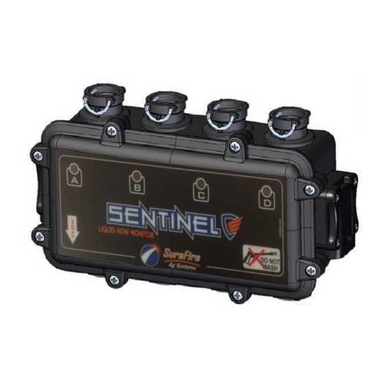
Figure 1: Front of 4 Row Sentinel Flow Module Figure 2: Plug in CAN DEVICE connector here.
SENTINEL QUICK START
396-3629Y1
Software Version 1.0.4
Figure 3: Run Screen
Advertisement
Table of Contents

Summary of Contents for Surefire SENTINEL
- Page 1 3. Connect next flow module in order, wait for about 30 seconds 4. Repeat until all modules have been connected Figure 1: Front of 4 Row Sentinel Flow Module Figure 2: Plug in CAN DEVICE connector here. Figure 3: Run Screen...
- Page 2 CONFIGURING ISO SENTINEL: 1. Press Tool Button to get to setup Button for Product 1 2. Setup Number of products (1 - 3) 3. Press the Product1, Product2, or Product3 brown box button in the middle of the screen to get into the Product Setup a.
- Page 3 OTHER NOTES: 1. The Sentinel Button always takes you back to the main run screen 2. The Implement button is used when Task Control is enabled to tell the system where your implement is in relation to the tractor. 3. The Following button contains the Speed Setup information.
- Page 4 Your tractor may use only one or all of these options may be available. iii. ECU input speed is a physical sensor input to the Sentinel ECU. Use a GPS pulse speed output to send a speed to this input. Then use the ECU speed calibration to adjust the speed to match actual tractor speed.
- Page 5 Auto Rate – AutoCalculates the rate based upon the average flow of all the rows. c. Prescription Rate is only available if Task Control has been enabled, display will send expected prescription rate to the Sentinel b. Simulate Flow is used for demoing and shows flows on the run screen when speed and section conditions are met.
- Page 6 Checking the box for Auto Scan will cause the Sentinel to switch pages automatically based on the time delay entered. b. Checking the box for Auto Scan rows will cause the Sentinel to switch the currently displayed row automatically to the next row based on the time delay entered.
- Page 7 7. To see row detail, click row to view and then press row view button in upper right corner. Second First 8. Alarms will activate even if the Sentinel Screens are not currently display and will look like the following...
- Page 8 9. LiquiShift Control, If LiquiShift is enabled on the product setup page, then the following Icon is available from the run screen a. The high and low pressure shift points can be adjusted by clicking on the setpoint and adjusting the value. This will move the red targets on the pressure gauge accordingly. b.


Need help?
Do you have a question about the SENTINEL and is the answer not in the manual?
Questions and answers