
Related Manuals for Illinois Tool Works ResMark 5000


Summary of Contents for Illinois Tool Works ResMark 5000
- Page 1 Operations Manual ResMark 5000 High-Resolution System 400386 Revision A 1 Missouri Research Park Drive • St. Charles, MO 63304 • Service Line 1-800-526-2531 Illinois Tool Works Inc © 2021...
- Page 2 The information contained in this manual is correct and accurate at the time of its publication. ITW reserves the right to change or alter any information or technical specifications at any time and without notice. ©2022 Illinois Tool Works Inc. All rights reserved...
- Page 3 The ResMark 5000 High-Resolution System, including all components unless otherwise specified, carries a limited warranty. The inks and conditioners used with the ResMark 5000 High-Resolution System carry a limited warranty. For all warranty terms and conditions, contact Diagraph, an ITW Company, for a complete copy of the Limited Warranty...
-
Page 4: Table Of Contents
Section 1: Safety and Ink Usage ..................................6 Section 2: Quick Start ......................................7 Step 1: Assemble Bracketry to Conveyor ..............................8 Step 2: Assemble Print Head onto Bracketry .............................9 Step 3: Mount and Connect Power Supply ...............................10 Step 4: Powering up the Print Heads ................................11 Step 5: Adjust Print Head to Substrate ..............................12 Step 6: Print Head Level and Tilt ................................13 Step 7: Install Ink Cartridge ..................................14... - Page 5 Appendix B: Theory of Operation ..................................36 Functional Description ....................................36 ResMark 5000 Mark 2 and Mark 4 Print System .............................36 ISM Features ......................................37 Ink States ........................................38 Print Head Daisy Chain ....................................39 Print Trigger Photosensor ..................................39 Encoder ........................................39 Appendix C: Diagrams .......................................40 ResMark 5000 Main CPU PCB Assembly ...............................40...
-
Page 6: Section 1: Safety And Ink Usage
ResMark 5000 High-Resolution Section 1: Safety and Ink Usage Section 1: Safety and Ink Usage Following is a list of safety symbols and their meanings, which are found throughout this manual. Pay attention to these symbols where they appear in the manual. -
Page 7: Section 2: Quick Start
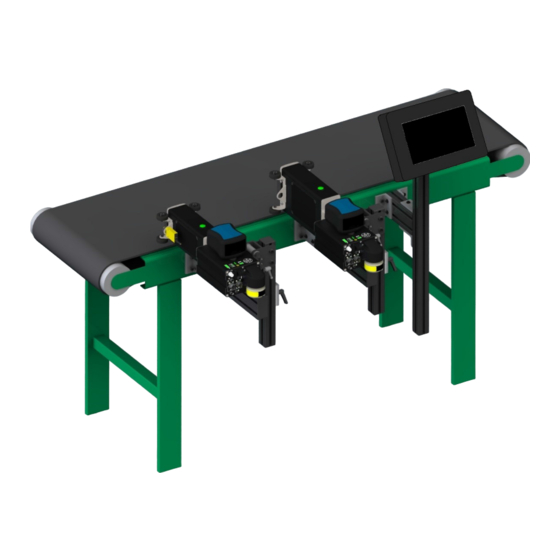
ResMark 5000 High-Resolution Section 2: Quick Start Section 2: Quick Start The figure at right illustrates a typical installation. System Components: 1. Bracketry Kit (Item 1) 2. Print Head (Item 2) 3. HMI (Item 3) 4. Power Supply (Item 4) 5. -
Page 8: Step 1: Assemble Bracketry To Conveyor
ResMark 5000 High-Resolution Section 2: Quick Start Step 1: Assemble Bracketry to Conveyor 1. Firmly tighten all fasteners. NOTE: Ensure bracketry is square and level. OPTIONAL HMI CONTROLLER / MOUNT PRINT HEAD CONVEYOR MOUNT (400201 FOR Mark 2 PRINT HEAD) -
Page 9: Step 2: Assemble Print Head Onto Bracketry
ResMark 5000 High-Resolution Section 2: Quick Start Step 2: Assemble Print Head onto Bracketry NOTE: The dovetail adapter and mounting bracketry can be mounted on either side of the print head system. DOVETAIL ADAPTER AND RETRACTING BRACKET AND CAN BE MOUNTED... -
Page 10: Step 3: Mount And Connect Power Supply
ResMark 5000 High-Resolution Section 2: Quick Start Step 3: Mount and Connect Power Supply 1. Install power supply with power cord mains facing the conveyor and DC output facing out towards the rear of the print system. 2. Firmly tighten fasteners to bracketry or convenient location. -
Page 11: Step 4: Powering Up The Print Heads
ResMark 5000 High-Resolution Section 2: Quick Start Step 4: Powering up the Print Heads 1. Install the power cord into the first print head in the system (from now on called the Primary print head). The power supply cable or jumper cable can be plugged into either power port. -
Page 12: Step 5: Adjust Print Head To Substrate
ResMark 5000 High-Resolution Section 2: Quick Start Step 5: Adjust Print Head to Substrate WASTE BOTTLE STATUS LED AT TEMPERATURE LED 1. Tighten bracketry to conveyor such that the print head is perpendicular to the carton; however, INK CARTRIDGE ALL CHANNEL STATUS LEDs ensuring that the print head is level from front to back. -
Page 13: Step 6: Print Head Level And Tilt
ResMark 5000 High-Resolution Section 2: Quick Start Step 6: Print Head Level and Tilt Print Head Level 1. Slightly loosen the Slide Bracketry Screws shown in the diagram in “Step 5: Adjust Print Head to Substrate” on page 12. 2. When the print head is perpendicular to the substrate, tighten the Slide Bracketry Screws. -
Page 14: Step 7: Install Ink Cartridge
ResMark 5000 High-Resolution Section 2: Quick Start Step 7: Install Ink Cartridge 1. Remove the shipping plugs from the rear and top of the Ink Supply Module. REMOVE Retain plugs for potential later use. 2. Install the ink cartridge and vent filter as shown. -
Page 15: Step 8: Priming The Print Head And Testing Print Quality
ResMark 5000 High-Resolution Section 2: Quick Start Step 8: Priming the Print Head and Testing Print Quality 1. Ensure all print heads are at operating temperature. SHIP CAP INSTALLED 2. Ensure that the shipping cap is installed for priming, otherwise ink will overflow and cause a mess. -
Page 16: Step 9: Mount Photosensor And Encoder
ResMark 5000 High-Resolution Section 2: Quick Start Step 9: Mount Photosensor and Encoder Photosensor 1. Mount the photosensor (kit 400203) in the roller bracket attached to the Printer Module and route the cable as shown in one of the two shown configurations depending on the application. -
Page 17: Step 10: Daisy-Chain Print Heads, Hmi, And/Or Customer Network
ResMark 5000 High-Resolution Section 2: Quick Start Step 10: Daisy-Chain Print Heads, HMI, and/or Customer Network OPTIONAL 1. Install secondary print heads as shown in the previous steps. 2. Secondary print heads should be connected between the upstream print head Ethernet out port to the input port on its print head as shown as shown in the diagrams below. - Page 18 ResMark 5000 High-Resolution Section 2: Quick Start Networked System with Optional HMI - One Print Head PRIMARY PRINT HEAD TO DOWNSTREAM PRINT FROM UPSTREAM HEAD OR HMI PRINT HEAD OR CUSTOMER NETWORK CUSTOMER NETWORK Networked System with Optional HMI - Two or More Print Heads...
-
Page 19: Step 11: Cap Unused Ports
ResMark 5000 High-Resolution Section 2: Quick Start Step 11: Cap Unused Ports After the installation is complete, it is recommended that all unused ports be capped to prevent accidental electrostatic discharge into a connector. The Primary print head should have all ports populated with a USB DEVICE OR cable. -
Page 20: Section 3: Maintenance And Shutdowns
ResMark 5000 High-Resolution Section 3: Maintenance and Shutdowns Section 3: Maintenance and Shutdowns Following are the recommended maintenance procedures to keep the ResMark 5000 High-Resolution system printing cleanly and efficiently. System Maintenance SHIPPING CAP STORAGE Intermittent (as required): 1. Be sure the photosensor is clean and free of debris. -
Page 21: Ink Supply Module Maintenance
ResMark 5000 High-Resolution Section 3: Maintenance and Shutdowns Ink Supply Module Maintenance Daily / Shift Startup / Periodic 1. Do not remove the ink cartridge. Use a low pressure air nozzle (5psi) and / or maintenance spray and a lint free cloth to remove debris buildup on and around the Ink Supply Module. -
Page 22: Cleaning Maintenance System
ResMark 5000 High-Resolution Section 3: Maintenance and Shutdowns Cleaning Maintenance System The cleaning system is an invaluable maintenance tool for routine cleaning of loose debris from the print engine orifice plate. The images below demonstrate print before and after the cleaning. -
Page 23: Printer Module Replacement
ResMark 5000 High-Resolution Section 3: Maintenance and Shutdowns Printer Module Replacement The normal life of a high-resolution piezoelectric printer is dictated by the amount of debris the orifice plate encounters during the coding application. Fine corrugate will fly into the orifice holes and clog / disrupt printing. Diagraph leverages the remanufacturability of its high- resolution technology by making it easy to remove the Printer Module on-the-fly and live (no need to disconnect ink or electrical lines). -
Page 24: Section 4: Troubleshooting
Section 4: Troubleshooting The ResMark 5000 ink jet system incorporates advanced designs, both in hardware and in software. However, if the system ever fails to perform properly, some built-in indicators will help in troubleshooting. This section will help minimize system downtime and explain some of the diagnostic features built into the system. - Page 25 ResMark 5000 High-Resolution Section 4: Troubleshooting Problem: Missing bottom print channels. Possible Cause: Ink build-up on lower orifices. Action: Check front to back level of print head. Problem: Fuzzy Print. Possible Cause: Print head too far away from substrate. Action: Move print head to within 1/8" from product.
- Page 26 ResMark 5000 High-Resolution Section 4: Troubleshooting Problem: Stretched out, light print, checkerboard pattern. Possible Cause: Incorrect encoder, or incorrect line speed (set too low) if using internal encoder. Action: Check for correct encoder (must use part # 400206). Problem: Short image, dark print, checkerboard pattern.
-
Page 27: System
ResMark 5000 High-Resolution Section 4: Troubleshooting System System Possible Review Observation Action Symptom Cause Check for Power LED to the Ink Supply Module. If No power from power Power Supply LED is not illuminated, check power supply LED and /... - Page 28 ResMark 5000 High-Resolution Section 4: Troubleshooting System Possible Review Observation Action Symptom Cause Replace Ink Supply Module LED8: Green; indicates a print head is signaling for PC Board the Vacuum Pump to turn on. Replace PCB Green Empty waste bottle Waste LED is red.
- Page 29 ResMark 5000 High-Resolution Section 4: Troubleshooting Photosensor Normal operation: • Photosensor plugged into the Primary print head. • The photosensor green power on LED is illuminated. • The photosensor yellow detect LED illuminates when an object is held between 5 mm - 100 mm (0.2 in - 4 in) from the face of the sensor.
-
Page 30: Appendix A: System Specifications
ResMark 5000 High-Resolution Appendix A: System Specifications Appendix A: System Specifications System 546mm 156mm [21.5in] [6.1in] 290mm [11.4in] 830mm 141mm [32.7in] [5.6in] 433mm [17.0in] 615mm [24.2in] 400386 Operations Manual Rev A Page 30... -
Page 31: Touch Pro 2 Hmi
ResMark 5000 High-Resolution Appendix A: System Specifications Touch Pro 2 HMI 2X M8 X 32mm 308.0mm [12.13in] 154.0mm [6.06in] [2X M8 X 1.25in] 38.1mm [1.50in] 225.0mm [8.86in] 93.4mm [3.68in] Size Fonts Electrical Weight: 2,18kg [5.5lb] True Type Input: 12VDC, 3A Height: 196,1mm [7.72in]... -
Page 32: Mark 2 Print Head
ResMark 5000 High-Resolution Appendix A: System Specifications Mark 2 Print Head Size - Mark 2 Head 167mm L: 447mm [17.6in] [6.6in] W: 66mm [2.6in] 104mm H: 117mm [4.6in] 117mm [4.1in] [4.6in] Weight: 2,7kg [6lbs] IP Rating IP65 (estimated) 121mm 231mm... -
Page 33: Mark 4 Print Head
ResMark 5000 High-Resolution Appendix A: System Specifications Mark 4 Print Head Size - Mark 4 Head L: 338,1mm [13.31in] 146mm [5.8in] W: 71,1mm [2.80in] 167mm [6.6in] 159mm H: 160,8mm [6.33in] [6.3in] Weight: 4,3kg [9.5lbs] IP Rating IP65 (estimated) 121mm 231mm 247mm [4.8in]... -
Page 34: System Interconnect Diagram
ResMark 5000 High-Resolution Appendix A: System Specifications System Interconnect Diagram 1. Mark 4 Print Head 2. Mark 2 Print Head 3. HMI 4. Conveyor 5. Product and Print Direction 6. Print Head Bracketry 7. Ink Status / Communications LED 8. Encoder 9. -
Page 35: Customer System Connection
ResMark 5000 High-Resolution Appendix A: System Specifications Customer System Connection USB DEVICE OR FIRMWARE UPGRADE PHOTOSENSOR ENCODER ETHERNET FROM UPSTREAM PRINT HEAD OR CUSTOMER NETWORK ETHERNET TO DOWNSTREAM PRINT HEAD OR HMI 24VDC POWER 400386 Operations Manual Rev A Page 35... -
Page 36: Appendix B: Theory Of Operation
ResMark 5000 Mark 2 and Mark 4 Print System The ResMark 5000 print system consists of an Ink Supply Module (ISM) and Printer Module (PM). The ISM is comprised of a Smart CPU printed circuit board, ink cartridge, ink manifold, ink pump, vacuum waste system, and male coupling. The PM contains a female receiver coupling, ink management fluidics, and piezoelectric print engine. -
Page 37: Ism Features
ResMark 5000 High-Resolution Appendix B: Theory of Operation ISM Features Recirculation WASTE BOTTLE AT TEMPERATURE LED STATUS LED This feature can only be controlled locally at the print head as the orifice shipping cap must INK CARTRIDGE ALL CHANNEL STATUS LEDs be aligned properly and securely mounted in place. -
Page 38: Ink States
ResMark 5000 High-Resolution Appendix B: Theory of Operation Ink States Normal Operation During Normal Operation, the Primary LED on top of the PM is illuminated green because there is at least 20% or more ink left in the cartridge, and the smart chip on the cartridge is being read properly. Print is always enabled in Normal Operation. -
Page 39: Print Head Daisy Chain
ResMark 5000 High-Resolution Appendix B: Theory of Operation Print Head Daisy Chain Print heads attach to the system (production line) in a daisy chain configuration via Ethernet or wireless. The Primary print head is the beginning of the daisy chain and has the photosensor plugged into it. All data is fed downstream from the primary print head to the daisy-chained heads. -
Page 40: Appendix C: Diagrams
ResMark 5000 High-Resolution Appendix C: Diagrams Appendix C: Diagrams ResMark 5000 Main CPU PCB Assembly Description Connector Description Connector Description LED1 Ethernet: ON = 100 Mbps; OFF = 10Mbps WIFI Dongle: USB Ink and Vacuum Pumps: 6-pin LED2 Ethernet: ON = 100 Mbps; OFF = 10Mbps... -
Page 41: Resmark 5000 Internal Wiring Diagram
ResMark 5000 High-Resolution Appendix C: Diagrams ResMark 5000 Internal Wiring Diagram MEMBRANE SWITCH & LED ARRAY SMART CHIP COUPLING INK WASTE PRINT ENGINE FLOAT SWITCH PRINTER MODULE PRIMARY LED INK RESERVOIR 24VDC FLOAT SWITCH VACUUM PUMP INK PUMP 400386 Operations Manual Rev A... -
Page 42: Appendix D: Ink
ResMark 5000 High-Resolution Appendix D: Ink Appendix D: Ink Storage Life of a FACTORY SEALED Bottle of Ink • ScanMark: 24 months from date of manufacture. • Store in a cool dry environment between 10°C - 32°C (50°F - 90°F). -
Page 43: Appendix G: Part Numbers
ResMark 5000 High-Resolution Appendix G: Part Numbers Appendix G: Part Numbers System Item Part No. Description 404050DG HMI / Controller 400001PDG Mark 2 Print Head, ScanMark (Domestic or European) 400004PDG Mark 4 Print Head, ScanMark (Domestic or European) 400386 Operations Manual Rev A... -
Page 44: Print Head Replacement Parts
Appendix G: Part Numbers Print Head Replacement Parts Item Part No. Description 400002PDG Ink Supply Module, ResMark 5000, ScanMark 400003PDG Printer Module, Mark 2, ScanMark (Domestic or European) 400005PDG Printer Module, Mark 4, ScanMark (Domestic or European) 400205 PCB, Rear Plate, & Vacuum Module Assembly... -
Page 45: Bracketry
ResMark 5000 High-Resolution Appendix G: Part Numbers Bracketry Item Part No. Description 400200 Mounting Bracket Kit with Retractor for Mark 2 or Mark 4 Print Head (Domestic or European) 400201 Mounting Bracket Kit with Retractor and Rollers for Mark 2 Print Head (Domestic or European) -
Page 46: Fittings
ResMark 5000 High-Resolution Appendix G: Part Numbers Fittings Part No. Description Contents Where Used 400223 Fitting, 400522, Luer Cap, Male 5 fittings per kit ISM vent port - storage 400224 Fitting, 400521, Luer, 90 degree 5 fittings per kit ISM vent port - while printing... -
Page 47: Service Parts And Optional Equipment
ResMark 5000 High-Resolution Appendix G: Part Numbers Service Parts and Optional Equipment Item Part No. Description 400203 Photosensor, Diffuse Type w/ 2ft Cable Encoder Assembly w/Mounting Bracket & 25ft 400206 Cable 400211 Beacon, Remote 400216 Plug, M8 Connector, pack of 10...
Need help?
Do you have a question about the ResMark 5000 and is the answer not in the manual?
Questions and answers