Table of Contents
Advertisement
Quick Links
SAFETY PRECAUTION FOR SERVICE MANUAL ............................................................................................................... 2
SPECIFICATIONS ................................................................................................................................................................. 3
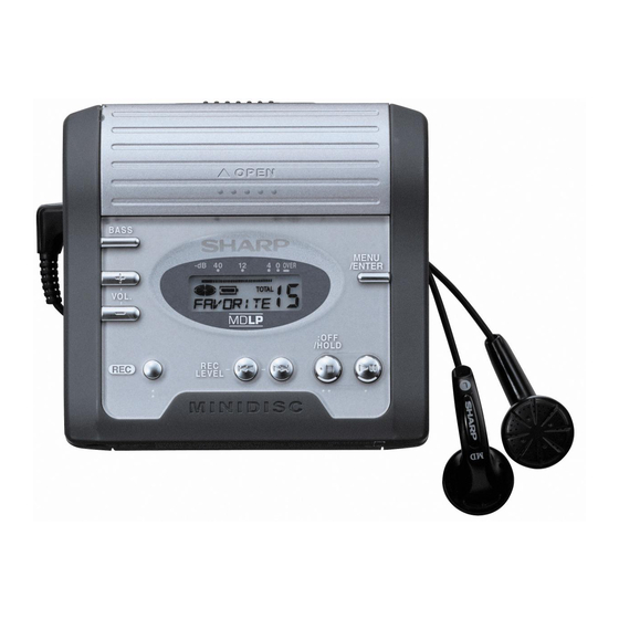
NAMES OF PARTS ............................................................................................................................................................... 4
DISASSEMBLY ...................................................................................................................................................................... 5
REMOVING AND REINSTALLING THE MAIN PARTS ......................................................................................................... 6
ADJUSTMENT ........................................................................................................................................................................ 7
MD ERROR MESSAGE DISPLAY CONTENT LIST ........................................................................................................... 21
NOTES ON SCHEMATIC DIAGRAM .................................................................................................................................. 22
TYPES OF TRANSISTOR AND DIODE .............................................................................................................................. 22
BLOCK DIAGRAM ............................................................................................................................................................... 23
SCHEMATIC DIAGRAM ...................................................................................................................................................... 24
WIRING SIDE OF P.W.BOARD ........................................................................................................................................... 32
VOLTAGE ............................................................................................................................................................................ 36
WAVEFORMS OF MD CIRCUIT ......................................................................................................................................... 37
TROUBLESHOOTING ......................................................................................................................................................... 38
FUNCTION TABLE OF IC .................................................................................................................................................... 41
PARTS GUIDE/EXPLODED VIEW
SERVICE MANUAL
PORTABLE MINIDISC RECORDER
MODEL
CONTENTS
SHARP CORPORATION
MD-MT270H(S)/(BK)
• In the interests of user-safety the set should be restored to its
original condition and only parts identical to those specified be
used.
This document has been published to be used
for after sales service only.
The contents are subject to change without notice.
MD-MT270H
No. SX299MDMT270H
Page
Advertisement
Table of Contents

Related Manuals for Sharp MD-MT270HS/BK


Summary of Contents for Sharp MD-MT270HS/BK
-
Page 1: Table Of Contents
TROUBLESHOOTING ................................. 38 FUNCTION TABLE OF IC ..............................41 PARTS GUIDE/EXPLODED VIEW PACKING OF METHOD (FOR U.K. ONLY) This document has been published to be used SHARP CORPORATION for after sales service only. The contents are subject to change without notice. -
Page 2: Safety Precaution For Service Manual
MD-MT270H SAFETY PRECAUTION FOR SERVICE MANUAL Laser Diode Properties Precaution to be taken when replacing and servicing the Material: GaAlAs Laser Pickup. Wavelength: 785 nm Pulse time: THE AEL (ACCESSIBLE EMISSION LEVEL) OF THE LASER Read mode: 0.8 mW Continuous POWER OUTPUT IS LESS THAN CLASS 1 BUT THE LASER Write mode: max 10 mW 0.5S... -
Page 3: Specifications
MD-MT270H FOR A COMPLETE DESCRIPTION OF THE OPERATION OF THIS UNIT, PLEASE REFER TO THE OPERATION MANUAL. SPECIFICATIONS Power source: DC 5 V: AC adaptor (AC 230 Output level: V, 50/60 Hz) Specified out- Maximum out- Load imped- DC 1.5 V: Commercially avail- put level ance able, "AA"... -
Page 4: Names Of Parts
MD-MT270H NAMES OF PARTS Main unit 1. Open Lever 2. Battery Cover 3. Menu/Enter Button 4. Stop/Power Off/Hold Button 5. Play/Pause Button 6. Bass/Delete/Synchro Button 7. Earphones/Line Output Socket 8. Volume/Cursor Buttons 9. Optical/Line Input Socket 10. Record/Track Mark Button 11. -
Page 5: Disassembly
MD-MT270H DISASSEMBLY Cares before disassembling When assembling the machine after disassembling or repair, observe the following requirements so as to ensure (A2) x1 ø1.4x4mm safety and performance. 1. Remove the batteries from the machine, and take out the Battery Door mini-disc. -
Page 6: Removing And Reinstalling The Main Parts
MD-MT270H REMOVING AND REINSTALLING THE MAIN PARTS Remove the mechanism according to the disassembling meth- (A2) x2 ods 1 to 4. (See Page 5.) ø1.4 x1.8mm How to remove the magnetic head (See Fig. 6-1.) Magnetic head 1. Remove the solder joints (A1) x 2 of the head flexible plate. Mechanism Flexible PWB Solder joints 2. -
Page 7: Adjustment
MD-MT270H ADJUSTMENT Test disc MD adjustment needs two types of disc, namely recording disc (low reflection disc) and playback-only disc (high reflection disc). Parts No. Type Test disc High reflection disc MMD-110 (TEAC Test MD) 88GMMD-110 Low reflection disc MMD-212 (TEAC Test MD) 74-minute disc 88GMMD-212 Low reflection disc MMD-213A (TEAC Test MD) 80-minute disc... - Page 8 MD-MT270H • Whenever the MENU button is pressed in the continuous Operation in each TEST mode playback mode, the indication changes as follows. 1. AUTO1 Mode * Pre-mastered disc • When the STOP button is pressed while the AUTO1 menu Continuous playback (SUBQ address indication) [ S Q appears or during automatic adjustment, the mode changes to the TEST mode stop state.
- Page 9 MD-MT270H 5. NORMAL Mode • When the STOP button is pressed while the NORMAL menu appears, the mode changes to the TEST mode stop state. • Indication during operation Indication of memory capacity on main unit LCD ] + Level meter : Internal mode : Address (Cluster section) : Address (Sector section)
- Page 10 MD-MT270H EEPROM (IC402) writing procedure 2. Temperature reference setting method 1. Procedure to replace EEPROM and write initial [1] Measurement, calculation and setting procedure value of microcomputer in EEPROM (1) Set the TEST mode. (1) Replace EEPROM. • Set TEST 1, 0 = '01', and turn on power (2) Refer to the latest EEPROM data list.
- Page 11 MD-MT270H EEPROM DATA LIST (EEPROM version d) Focus setting Spindle setting Item display Set values Item display Set values F G 1 _ S P G _ F G 2 _ S P i F F 0 _ S P m _ F F 1 _ S P o _ F F 2 _...
- Page 12 MD-MT270H Bass setting Control setting Item display Set values Item display Set values B S 0 _ C T 0 _ B S 1 _ C T 1 _ B S 2 _ C T 2 _ B S 3 _ C T 3 _ U S A _ B S 4 _...
- Page 13 MD-MT270H Test Mode Change Chart Test Mode Menu T E S T : Test Mode STOP FAST FORWARD FAST REVERSE Slide external Slide internal periphery move periphery move BASS FAST REVERSE A U T O 1 : Pre-auto adjustment menu FAST FORWARD FAST REVERSE A U T O J...
- Page 14 MD-MT270H ATT Auto Adjustment A U T O 2 : ATT auto adjustment menu PLAY A T 2 : During ATT auto adjustment Adjustment error A D J . N G Normal end : ATT adjustment error (adjustment value output) A D J .
- Page 15 MD-MT270H Continuous Rrecord • Continuous record from the current pickup position R E C : Continuous record menu PLAY : Continuous record A P # # # # # # # #: Address • Continuous record playback from any address R E C : Continuous record menu PLAY...
- Page 16 MD-MT270H Error History Display • Error history clear D A T A : Error history display menu MENU C L E A R : Error history clear • Error history display D A T A : Error history display menu PLAY E 0 §...
- Page 17 MD-MT270H Focus Setting : Focus setting menu F o c u s PLAY FAST FORWARD FAST REVERSE FAST FORWARD FAST REVERSE F G 1 F Z H F G M FAST FORWARD FAST REVERSE FAST FORWARD FAST REVERSE FAST FORWARD FAST REVERSE F G 2 F L n...
- Page 18 MD-MT270H Tracking Setting : Tracking setting menu T r a c k PLAY FAST FORWARD FAST REVERSE FAST FORWARD FAST REVERSE T B t C L r T G 1 FAST FORWARD FAST REVERSE FAST FORWARD FAST REVERSE FAST FORWARD FAST REVERSE T G 2 T K o...
- Page 19 MD-MT270H TEMP Setting T e m p : Temp setting menu PLAY : TEMP reference T M § § : Reference FAST FORWARD FAST REVERSE § § : Temperature code : TEMP A/D input value T p i n : Measurement value * When the [STOP ] button is pressed in specific menu, the "TEST MODE STOP"...
- Page 20 MD-MT270H Control Setting : Control setting menu C T R L PLAY FAST REVERSE FAST FORWARD FAST REVERSE FAST FORWARD C T 0 B U 0 R 2 0 FAST FORWARD FAST REVERSE FAST REVERSE FAST FORWARD FAST REVERSE FAST FORWARD R 2 1 C T 1 B D 0...
-
Page 21: Md Error Message Display Content List
MD-MT270H MD ERROR MESSAGE DISPLAY CONTENT LIST Remarks Error content Error code Display content Can' t READ* Readout of the information is not completed. f: Focus error r: READ ERR Can' t READ* Readout of the TOC information * indicates the detailed factor. s: Search time over is not completed. -
Page 22: Notes On Schematic Diagram
MD-MT270H NOTES ON SCHEMATIC DIAGRAM • Resistor: • The indicated voltage in each section is the one measured To differentiate the units of resistors, such symbol as K and by Digital Multimeter between such a section and the chas- M are used: the symbol K means 1000 ohm and the symbol sis with no signal given. -
Page 23: Block Diagram
MD-MT270H VCC+2.5V DCVDD DCEXT PCNT3 PCNT1 +4.5V Figure 23 BLOCK DIAGRAM – 23 –... -
Page 24: Schematic Diagram
MD-MT270H Serial No.21100001~21102500 IC354 CPH5608 HEAD DRIVER TP661 TP660 TP659 TP658 C351 TP657 33P(CH) TP656 TP655 TP654 TP653 TP652 TP651 TP351 C613 R604 330K T– F– FODRF FODRR C604 PGND1 C605 SLGND L604 OUT1R IN1F 22µH SUCO SVCO OUT1F IN1R L603 C603 SWCO... - Page 25 MD-MT270H TP101 LDVAR TP102 LDON TP103 DGND L101 100mA DGND TP105 TP106 TP107 TP108 CVCC MP/R TP110 TP111 TP112 AGND TP114 TP115 TP116 TP117 TP118 TP119 TP120 TP121 T– F– R134 R132 C114 5P(CH) BOUT R111 EOUT R135 C112 0.033 C107 R137 0.033...
- Page 26 MD-MT270H Serial No.21100001~21102500 R411 100K R423 TP407 R425 C431 0.47 AURESET C839 0.33 C853 +2.5V 220/4V R855 330K C852 –2.5 22/6.3V D861 DG1H3 C862 C848 C847 C846 C830 VCCMICOM C843 0.22 C842 33/6.3V C850 C869 47/6.3V RCAULT TP771 C841 AUSCLK AUDATA TP841 PBMUTE...
- Page 27 MD-MT270H R411 100K IC203 62FP1602 C206 REGULATOR TP407 R218 330K C431 0.47 AURESET VCCADDA –2.5 ADDATA(ADC) C773 0.22 C243 470P C504 SDTO 3.3/10V BCLK MCLK LRCK VCOM C503 CDTI RIN2 3.3/10V CCLK LIN2 RIN1 LIN1 C869 47/6.3V C241 C242 RCAULT TP771 AUSCLK AUDATA...
- Page 28 MD-MT270H Serial No.21102501~ IC354 CPH5608 HEAD DRIVER TP661 TP660 TP659 TP658 C351 TP657 33P(CH) TP656 TP655 TP654 TP653 TP652 TP651 TP351 C613 R604 330K T– F– FODRF FODRR C604 PGND1 C605 SLGND L604 OUT1R IN1F 22µH SUCO SVCO OUT1F IN1R L603 C603 SWCO...
- Page 29 MD-MT270H LDVAR TP101 TP102 LDON DGND TP103 L101 100mA DGND TP105 TP106 TP107 TP108 CVCC TP110 MP/R TP111 TP112 AGND TP114 TP115 TP116 TP117 TP118 TP119 TP120 T– TP121 F– R134 R132 C114 5P(CH) BOUT R111 EOUT R135 C112 0.033 C107 R137 0.033...
- Page 30 MD-MT270H Serial No.21102501~ R411 100K R423 TP407 R425 C431 0.47 AURESET C839 0.33 C853 +2.5V 220/4V R855 330K C852 –2.5 22/6.3V D861 DG1H3 C862 C848 C847 C846 C830 VCCMICOM C843 0.22 C842 33/6.3V C850 C869 47/6.3V RCAULT TP771 C841 AUSCLK AUDATA TP841 PBMUTE...
- Page 31 MD-MT270H R411 100K IC203 62FP1602 C206 REGULATOR TP407 R218 330K C431 0.47 AURESET VCCADDA –2.5 ADDATA(ADC) C773 0.22 C504 SDTO 3.3/10V BCLK MCLK LRCK VCOM C503 CDTI RIN2 3.3/10V CCLK LIN2 RIN1 LIN1 C869 47/6.3V RCAULT TP771 AUSCLK AUDATA PBMUTE BEEP C760 R757 R504...
-
Page 32: Wiring Side Of P.w.board
MD-MT270H Serial No.21100001~21102500 MAIN PWB-A (BOTTOM VIEW) J701 J703A OPTICAL PHONES /LINE IN IC244 TP729 TP665 TP804 L452 R768 R403 J801 L453 SW601 DC IN 5V TP724 DISC D496 C840 PROTECT C242 TP453 TP801 TP452 R716 IC245 TP459 R504 C510 TP500 TP707 Q801... - Page 33 MD-MT270H Serial No.21102501~ MAIN PWB-A (BOTTOM VIEW) J701 J703A OPTICAL PHONES /LINE IN TP729 TP665 TP804 L452 R768 R403 J801 L453 SW601 DC IN 5V TP724 DISC D496 C840 PROTECT TP453 TP801 TP452 R716 TP459 R504 C510 TP500 TP707 Q801 C774 R833 R854...
- Page 34 MD-MT270H MAIN PWB-A (TOP VIEW) J701 OPTICAL J703A /LINE IN PHONES R767 CHASSIS L800 J801 R765 DC IN 5V D801 L454 C712 SW453 SW451 SW452 D495 BASS/SYNC VOL+ VOL– C715 R718 R811 IC873 R809 SW459 BATTERY TERMINAL (212) C836 C504 Q804 IC803 C503...
- Page 35 MD-MT270H P34 2-D TO MAIN PWB CN601 M902 MAGNETIC HEAD (16) SLED MOTOR MECHANISM FLEXIBLE PWB (15) M901 SPINDLE MOTOR M903 LIFT MOTOR P34 3-D TO MAIN PWB CN482 LCD UNIT (218) OPTICAL PICKUP (1) CN101 P34 3-F TO MAIN PWB Figure 35 WIRING SIDE OF P.W.BOARD (4/4) –...
-
Page 36: Voltage
MD-MT270H VOLTAGE IC101 IC201 IC401 IC703 IC601 IC809 VOLTAGE PIN VOLTAGE PIN VOLTAGE PIN VOLTAGE VOLTAGE VOLTAGE VOLTAGE VOLTAGE VOLTAGE (0V) 0.73V 1.20V 2.49V 0.76V (0V) 0.73V 2.53V 2.49V 1.99V 0.76V 1.27V 0.73V (2.52V) 1.27V 2.46V 2.49V 1.99V 2.53V 0.73V 2.49V 1.99V 4.6V... -
Page 37: Waveforms Of Md Circuit
MD-MT270H WAVEFORMS OF MD CIRCUIT Stopped 1994 / 12 / 16 00:24:17 Stopped 1994 / 12 / 15 22:54:19 Stopped 1994 / 12 / 16 01:03:40 CH1=1mV CH2=500mV CH3=5V CH4=2V 50ms/div CH1=2V CH2=2V CH3=2V CH4=2V 50us/div CH1=1V CH2=2V CH3=500mV 2ms/div DC 10:1 DC 10:1 DC 10:1... -
Page 38: Troubleshooting
MD-MT270H TROUBLESHOOTING It is advisable to use the TEST mode (refer to Error Data Display Mode, P12) indicating the causes of troubles before starting repair. Causes of operation errors (up to 10 errors) are recorded as error codes. This information is useful for repair. - Page 39 MD-MT270H • Audio playback circuit Although the playback time display is acting., no sound is given during playback in the normal mode. Is PWM signal output from IC501 pins 68, 69, 72, 73? Check the periphery of IC501. Is audio waveform output from IC703 pins 8 and 17. Check the periphery of IC703.
- Page 40 MD-MT270H • Recording/playback operation. Insert a low reflection disc, and ascertain audio output by normal playback, and then set TEST REC mode. Change MSL from 00H to 80H by the control setting of EEPROM. After completing the operation, return in to 00H. Check voltage of pins 89 and 90 of IC201, pins 17, 18, 20, and Does the head move down, failing to start record even 21 of IC601, pins 8 and 9 of CN601.
-
Page 41: Function Table Of Ic
MD-MT270H FUNCTION TABLE OF IC IC401 RH-iX0561AWZZ :System Microcomputer (IX0561AW) (1/2) Pin No. Port Name Terminal Name Input/Output Function P9_4/DA1 MCMON Output Internal operation status monitor P9_3/DA0 LDVAR Output P.U. laser power setting output P9_2 EPRT Output EEPROM write protection TB1IN SPIN Input/Output... - Page 42 MD-MT270H IC401 RH-iX0561AWZZ :System Microcomputer (IX0561AW) (2/2) Port Name Terminal Name Input/Output Function Pin No. P4_1 SLCNT3 Output Stepping control 3 P4_0 DISCPR Input Disc record inhibition switch input P3_7 PBLAT Output Audio IC data latch output P3_6 RFPCNT Output RF control P3_5 RADAT...
- Page 43 MD-MT270H IC201 VHiLR37819+-1 :Endec/Servo/Atrac (LR37819) (Serial No.21100001~21102500) IC201 VHiLR37820+-1 :Endec/Servo/Atrac (LR37820) (Serial No.21102501~) System LSI expansion output port Port Name Terminal Name Input/Output Pin No. Function Remarks EXPORT4 LDCNT1 Output Recording head raising-lowering control output 1 See the separate table *2. EXPORT5 LDCNT2 Output...
- Page 44 MD-MT270H IC601 VHiLV8221T+-1 :PWM/Motor Driver (LV8221T)(1/2) Pin No. Terminal Name Function SPGND Ground terminal of spindle output. SPVS Power supply terminal for spindle drive . The capacitor is connected to the GND terminal. Position detection comparator filter terminal in the spindle motor. The capacitor is connected between this terminal and COMIN terminal (pin).
- Page 45 MD-MT270H IC601 VHiLV8221T+-1 :PWM/Motor Driver (LV8221T)(2/2) Pin No. Terminal Name Function SLVS Drive power terminal in 3-phase thread section. The capacitor is connected to the GND terminal. FG pulse output terminal (MOS output). It outputs the pulse equivalent to 3-hole. SLGND 3-phase thread output section GND terminal.
- Page 46 MD-MT270H IC202 RH-iX2960AFZZ: 16M Bit D-RAM (IX2960AF) Function Terminal Name Pin No. Power supply (2.6V) I/O1 Data input/data output I/O2 Data input/data output Write enable Low address strobe Not connected Address input 8-11 A0-A3 Address input Power supply (2.6V) Ground (0V) 14-19 A4-A9 Address input...
- Page 47 “HOW TO ORDER REPLACEMENT PARTS” To have your order filled promptly and correctly, please furnish the For U.S.A. only following information. Contact your nearest SHARP Parts Distributor to order. 1. MODEL NUMBER 2. REF. No. 3. PART NO. 4. DESCRIPTION For location of SHARP Parts Distributor, Please call Toll-Free;...
- Page 48 MD-MT270H PRICE PRICE DESCRIPTION PARTS CODE DESCRIPTION PART CODE RANK RANK AC 100 µH L860 VPCBM101K0000 INTEGRATED CIRCUITS VIBRATORS IC101 VHIIR3R58M/-1 AM RF Signal Processor,IR3R58M IC201 VHILR37819+-1 BK Endec/Servo/Atrac,LR37819 [Serial No.21100001~ XL201 RCRSC0028AFZZ AH Crystal,33.8688 MHz 21102500] XL401 RCRM-0050AWZZ AE Ceramic,Osillator,4 MHz IC201 VHILR37820+-1 BK Endec/Servo/Atrac,LR37820...
- Page 49 MD-MT270H PRICE PRICE DESCRIPTION PART CODE PARTS CODE DESCRIPTION RANK RANK AC 1 µF,6.3V C836,837 VCKYCY0JB105K R467 VRS-CY1JB223J AA 22 kohms,1/16W AC 0.33 µF,10V C839 VCKYCY1AB334K R481 VRS-CY1JB333F AA 33 kohms,1/16W AD 220 µF,4.0V,Electrolytic C840 VCEAPW0GW227M J R482,483 VRS-CY1JB183F AA 18 kohms,1/16W AC 1 µF,6.3V C841 VCKYCY0JB105K...
- Page 50 MD-MT270H PRICE PRICE DESCRIPTION PART CODE PARTS CODE DESCRIPTION RANK RANK MLEVF0112AWFW J AC Lever,Lift LX-BZ0063AWFC AB Screw,ø1.4×2.5mm MSPRP0060AWFJ J AB Spring,Thrust LX-BZ0063AWFC AB Screw,ø1.4×2.5mm [S] MSPRP0067AWFJ J AB Spring,Drive Grip LX-BZ0063AWF6 AD Screw,ø1.4×2.5mm [BK] MSPRT0058AWFJ J AB Spring,Eject Lever LX-BZ0960AFZZ AB Screw,ø1.4×1.5mm NBRGC0004AWZZ J...
- Page 51 MD-MT270H 503x2 501x3 506x2 M902 M901 M903 Figure 4 MD MECHANISM EXPLODED VIEW – 4 –...
- Page 52 MD-MT270H 602x2 PWB-A 603x2 602x2 MECHANISM 603x2 Figure 5 CABINET EXPLODED VIEW – 5 –...
-
Page 53: Packing Of Method (For U.k. Only)
MD-MT270H PACKING OF METHOD (FOR U.K. ONLY) 1. Connecting Cord,RCA Type QCNWG0029AWZZ 9. Operation Manual TINSE0488AWZZ 2. AC Adapter RADPA8058AWZZ 10. Quick Guide TINSE0489AWZZ 3. Headphones RPHOH0011AWZZ 12. Label,Bar Code [K] TLABE0711AWZZ 4. Packing Case [K] SPAKC1541AWZZ 12. Label,Bar Code [S] TLABE0726AWZZ 14. - Page 54 MD-MT270H — M E M O —...
- Page 55 MD-MT270H — M E M O —...
- Page 56 MD-MT270H © COPYRIGHT 2002 BY SHARP CORPORATION ALL RIGHTS RESERVED. No part of this publication may be reproduced, stored in a retrieval system, or transmitted in any form or by any means, electronic, mechanical, photocopying, recording, or otherwise, without prior written permission of the publisher.
Need help?
Do you have a question about the MD-MT270HS/BK and is the answer not in the manual?
Questions and answers