Table of Contents
Advertisement
Quick Links
Advertisement
Table of Contents

Related Manuals for Olink Signature Q100

Summary of Contents for Olink Signature Q100
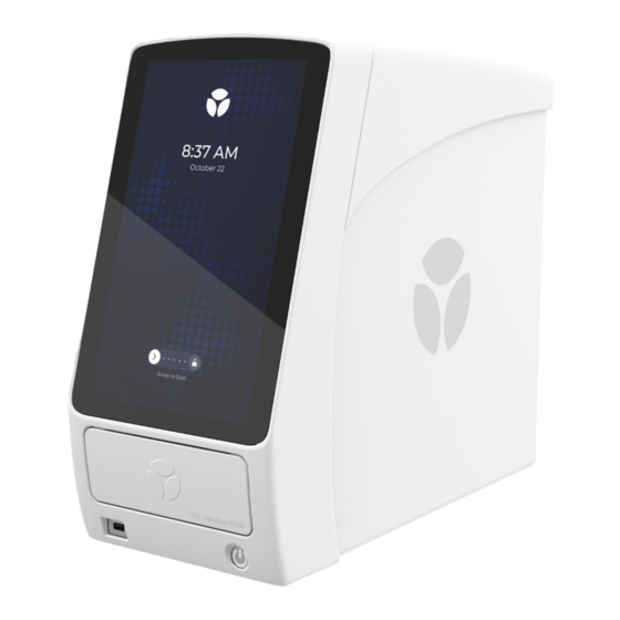
- Page 1 ® Olink® Signature Q100 Installation Procedure 1171, v1.1, 2022-01-25...
-
Page 2: Table Of Contents
Table of contents 1. Introduction ............................3 1.1 About This Guide and Target Group ................3 2. Safety ..............................4 2.1 Instrument Safety .......................4 2.2 Electrical Safety ........................4 2.3 Chemical Safety ........................4 3. Installation .............................5 3.1 Workflow ..........................5 3.2 Delivery and System Inspection ..................6 3.3 Uncrate the Instrument .................... -
Page 3: Introduction
About This Guide and Target Group This document describes how to unpack and install the Olink® Signature Q100 instrument at the customer's site. If assistance for lifting, installation qualification (IQ) or operational qualification (OQ) is needed, please contact our support:... -
Page 4: Safety
2. Safety Instrument Safety The system should be serviced by authorized personnel only. For complete instrument safety information, including a full list of the symbols on the instrument, refer to the Olink® Signature Q100 User Manual (1172). WARNING: PHYSICAL INJURY HAZARD. 2-person lift. Use proper lifting techniques. -
Page 5: Installation
Proper installation of the instrument is essential to ensure optimal performance of the instrument. he customer is responsible for the site to be compliant with site preparation and requirements as described in the Olink® Signature Q100 Site Requirements Guide (1170) before the instrument is installed. -
Page 6: Delivery And System Inspection
250 V/8 A, 18 AWG, and have a length not exceeding 2.5 meters. Olink®Signature Q100 The Olink Signature Q100 Interface Plates are specific to the type of Interface Plate kit integrated fluidic circuit (IFC, also referred to as a chip) you are using. -
Page 7: Uncrate The Instrument
The system’s packaging is designed to protect the instrument during shipment when routine handling and transport instructions are followed. NOTE: Always contact an Olink representative before moving the instrument. Failure to do so may invalidate the warranty. 1. Cut the shipping straps and lift the box to expose the instrument. - Page 8 3. Lift and remove the foam enclosure to reveal the instrument. Figure 4. Instrument with plastic wrapping 4. With the assistance of at least one more person, lift the instrument by the rear handle and the pocket underneath the bottom front of the instrument. Place the instrument onto the workbench. Figure 5.
-
Page 9: Remove The Shipping Lock Screw
Remove the Shipping Lock Screw AUTION: Removing the enclosure creates a potential shock hazard from exposed internal components. Ensure the instrument is unplugged from the power source before beginning this procedure (as in figure herebelow). 1. Carefully turn the instrument around. Locate and remove the two (2) Phillips screws at the rear of the top panel of the instrument by using a #2 Phillips screwdriver. - Page 10 3. Loosen the two (2) thumbscrews at the rear left of the instrument panel. Figure 13. Thumbscrews NOTE: The thumbscrews cannot be removed completely but will still be attached. 4. Gently slide the left side panel back from the instrument and remove it. Figure 14.
- Page 11 5. Locate the red shipping lock located internally just inside the black optical enclosure on the left side of the instrument. We recommend that you attach the screw to the neighbouring whole (see figure), as it will need to be reinstalled if the instrument is to be relocated or shipped in the future.
- Page 12 3.4.1 Reinstall the Top and Side Panels 1. Reinstall the left side panels, matching the left side panel mounting holes with the aligning pin in the instrument’s front side. Figure 18. Left side panel installation Figure 19. Side panel aligning pin 2.
-
Page 13: Connect The Ethernet Cable (Optional)
NPX Signature software. You can optionally enable remote technical support, connecting the instrument to your network by using an ethernet cable. For more information on how to securely connect the Signature Q100 to a network, refer to Olink® Signature Q100 User Manual (1172) and Olink® NPX Signature User Manual (1173). -
Page 14: Installation And Configuration
3.6 Installation and Configuration 1. Attach the power cord at the rear panel of the instrument and connect to an electrical outlet. The instrument is ready to be powered on by toggling on the power switch located above the power cord. ELECTRICAL HAZARD: Plug the system into a properly grounded receptacle with adequate current capacity. - Page 15 3. After the system starts up, the screen prompts you to begin by tapping Next . Figure 26. Welcome screen 4. To perform the installation: Follow the instructions on the touch screen. 5. Set the time zone by scrolling to and selecting the desired time zone setting. Confirm the selection by tapping OK. Tap Next.
- Page 16 6. Set the time and date by scrolling to the correct values. Tap Next. Figure 29. Set Date and Time Figure 30. Select Date and Time 7. Set the Authentication and Domain for IT directory identification. Uncheck the Require Authentication checkbox to proceed without authentication.
- Page 17 8. Follow the prompts to remove the shuttle compartment packing material and tape. Figure 32. Shuttle packing material removal NOTE: Store the shuttle packing materials with the rest of the instrument packaging. 9. Remove the tape across the lid, and open the shuttle door by pulling down on the plastic tab. Remove the shuttle compartment packing material.
- Page 18 NOTE: If self-diagnostics fails, re-run a second time again. If the self-diagnostics fails again, please contact Olink support. AUTION: PINCH HAZARD. The instrument door and tray can pinch your hand. Make sure your fingers, hands, and shirtsleeves are clear of the door and tray when loading or ejecting a chip.
- Page 19 The installation checklist consists of the following checkpoints: • Site Requirements defined in document Olink® Signature Q100 Site Requirements (1170) have been met • No visible damage to shipment received • Power cable and 96.96 Interface plate received • Transport packing material and restraints removed as defined in Installation Procedure •...
- Page 20 NOTE: If the Installation Instrument Check fails, a notification appears. Contact Olink for tech support. Figure 40. Initialization Failed Notification Figure 42. Run Instrument Check Figure 41. Run Instrument Check...
- Page 21 Figure 43. Swipe to Unlock Figure 44. Start a new run NOTE: To perform a Focus or Target 48 run, you need the 24.192 Interface Plate or 48.48 Interface Plate, respectively. These interface plates can be purchased separately from Olink.
-
Page 22: Revision History
All information in this publication is subject to change without notice. Trademarks: Olink and the Olink logo are trademarks and/or registered trademarks of Olink Proteomics AB in the United States and/or other countries. All other trademarks are the sole property of their respective owners.