Table of Contents
Advertisement
Quick Links
OPERATOR'S MANUAL
SAFETY INSTRUCTIONS
WITH INSPECTION AND MAINTENANCE INSTRUCTIONS
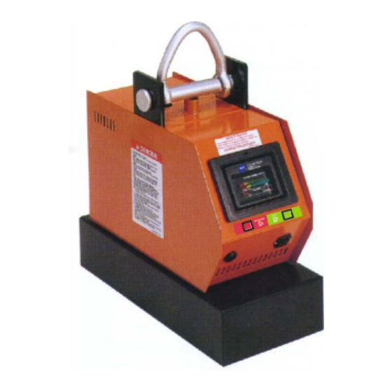
BATTERY POWERED LIFT MAGNETS
BUX BM
-13PB
2
BUX BM
-50PB
2
■
Always stay clear
of the load.
AND
MODELS: BUX BM
BUX BM
BUX BP
ADANGER
■
Never lift loads over
people or in close
proximity to people.
& BUX BP
2
2
-25PB
2
-7PB
2
■
Never attempt to operate either of
these magnets until you have read and
understand this Operator's Manual.
BUX BM
-36PB
2
BUX BP
-15PB
2
Advertisement
Table of Contents

Related Manuals for Walker Magnetics BUX BM2


Summary of Contents for Walker Magnetics BUX BM2
- Page 1 OPERATOR'S MANUAL SAFETY INSTRUCTIONS WITH INSPECTION AND MAINTENANCE INSTRUCTIONS BATTERY POWERED LIFT MAGNETS MODELS: BUX BM & BUX BP BUX BM -13PB BUX BM -25PB BUX BM -36PB BUX BM -50PB BUX BP -7PB BUX BP -15PB ADANGER ■ ■ ■...
-
Page 2: Table Of Contents
CONTENTS INTRODUCTION ..................................2 SAFETY INSTRUCTIONS ..............................3 GENERAL SAFETY RULES ................................. 3 RECOGNIZE SAFETY INFORMATION ............................4 UNSAFE LIFTING APPLICATIONS FOR YOUR MAGNET ......................4 WAYS TO AVOID A REDUCTION OF LIFTING CAPACITY ......................5 ADDITIONAL WARNINGS ................................5 SAFETY PERSON .................................. -
Page 3: Safety Instructions
SAFETY INSTRUCTIONS GENERAL SAFETY RULES Danger always exists when loads are transported by lifting devices, especially if the equipment is not being used properly or is poorly maintained. Because accidents and severe bodily injury or death can result, specific safety precautions must be applied to the operation, inspection, and maintenance of Walker Lift Magnets. -
Page 4: Recognize Safety Information
SAFETY INSTRUCTIONS RECOGNIZE SAFETY INFORMATION This is the safety alert symbol. When you see this symbol on your magnet or in this manual, be alert to the potential for per sonal injury. Follow recommended precautions and safe operat- ing practices at all times. This indicates a situation in which a hazard DANGER is imminent and will result in a high prob... -
Page 5: Ways To Avoid A Reduction Of Lifting Capacity
SAFETY INSTRUCTIONS WAYS TO AVOID A REDUCTION OF LIFTING CAPACITY ADANGER To Avoid any Reduction of Lifting Capacity: ■ The lifting surfaces of the magnet and the area of the load where the magnet will be located must be clean, smooth, flat and free of nicks and burrs. -
Page 6: Installation
INSTALLATION BATTERY INSTALLATION: The battery used in the BUX BM -13PB series should be a BCI group 22NF style battery of the deep discharge type. It should have a minimum reserve capacity of 45 ampere-hour @ 20 hour rate (e.g. Dynasty DCS-50U). The battery used in the BUX BM -25PB, BUX BM -36PB, BUX BM... -
Page 7: Specifications
SPECIFICATIONS Magnet Specifications Model No. BUX BM -13PB BUX BM -25PB BUX BM -36PB BUX BM -50PB BUX BP -7PB BUX BP -15PB Length (inch) 21.00 21.00 48.00 60.00 20.50 30.00 Width (inch) 9.56 9.63 9.63 12.00 9.50 10.50 Ht. (inch)To Crane Hook 22.28 22.46 23.15... -
Page 8: Operating Instructions
OPERATING INSTRUCTIONS IMPORTANT FACTS FOR THE OPERATION OF LIFT MAGNETS LOAD CHARACTERISTICS OTHER THAN JUST WEIGHT MUST BE CONSIDERED IN ORDER TO DETERMINE THE LOAD THAT ANY MAGNET CAN LIFT. This statement is true for all lifting magnets because they all operate using the same fundamental laws of physics. - Page 9 4. LOAD LENGTH OR WIDTH As the length or width of a load increases, it will cease to remain flat when lifted as the edges will begin to droop. This drooping or sagging of the load can create an air gap between the load and the magnet, especially at the ends of the magnet.
- Page 10 SAFETY FOR FAST, EASY LIFTING WITH YOUR WALKERLIFT MAGNET - NEVER attempt to operate this lift magnet until you read and understand the OPERATOR'S MANUAL & SAFETY INSTRUCTIONS (Manual #37-D016630 Check the condition of the magnet prior to every lift. WIPE clean the bottom of the magnet for the BM and BP magnets).
- Page 11 RULES MODELS: BUX BM and BUX BP This magnet can be operated from r..��?A-< "'- the controls located on the front P----.. panel of the magnet or the Remote Control unit when its lens is pointed towards the control panel on the magnet. To energize the magnet, push the "LIFT"...
-
Page 12: Recommended Lifting Procedures
RECOMMENDED LIFTING PROCEDURES ■ SAFETY HOOK LATCH Always use a safety hook latch on your crane hook to hold your magnets. ■ STAY CLEAR OF TH E LOAD Guide the load by pushing or pulling the edges of the load. Keep your entire body clear of the load at all times. -
Page 13: Guidelines For The Reduction Of The Rated Lifting Capacity
GUIDELINES FOR THE REDUCTION OF THE RATED LIFTING CAPACITY: Each Walker lifter model is rated for a different weight limit. Load characteristics CAUTION lwill affect the lifting capacity of the magnets. The lifting guidelines f o r the various models are shown on the following pages. ■... - Page 14 LOAD WEIGHT GUIDELINE To estimate the weight of a steel work piece, first determine the volume of the Load in cubic inches. Then multiply the volume (cubic inches) by the density of steel (.283) pounds per cubic inch. Load Weight (steel)= (volume) multiplied by (density) = (W (.283) Example: What is the weight of a 1 O"...
- Page 15 LIFTING GUIDELINES BM PLATE TYPE OF SURFACE CLEAN & SMOOTH RUST OR SCALE IRREGULAR OR ROUGH MAGNET WORKPIECE Simila r to a fla t groun d surfa c e Simila r to a fla t ho t rolle d s t eel Simila r to a fla t smoo t h cu t MODELS THICK NESS...
-
Page 16: Lifting Guidelines Bp Plate
LIFTING GUIDELINES BP PLATE TYPE OF SURFACE CLEAN & SMOOTH RUST OR SCALE IRREGULAR OR ROUGH MAGNET WORKPIECE Simila r to a flat gro und surface 32 Simila r to a flat ho t rolle d s teel Simila r to a flat s moo th c u t MODELS THICK NESS surface . -
Page 17: Indicating Lamps, I.r. Remote, And Local Control
INDICATING LAMPS, I.R. REMOTE, and LOCAL CONTROL A DANGER Do Not Attempt To Lift a Load While Alarm Is Sounding Or Red "Danger" Indicator Is On. INDICATOR LIGHT DISPLAY DURING LIFT When the magnet is on a load and the "LIFT" button on the Front Panel or I.R. remote is pressed, the red "DANGER"... -
Page 18: I.r. Remote
I.R. REMOTE TURN ON MAGNET Press the green LIFT button. The red DANGER indicator will light and the alarm will sound. This alarm may continue, for a few seconds until the magnetic energy builds up to the proper level needed for lifting. -
Page 19: Inspection And Maintenance Instructions
INSPECTION AND MAINTENANCE INSTRUCTIONS - ------- EVERY LIFT - ------ - ■ Keep the lifting surfaces of the magnet CLEAN, SMOOTH, FLAT, and FREE OF RUST or any FOREIGN MATERIALS. Nicks and burrs on the lifting surfaces will reduce lifting capacity. -
Page 20: Periodic Inspection Record
PERIODIC INSPECTION RECORD See ASME 830.20 Section 20 Record date and initials; note condition of each item Date and Initial for each inspection Condition Date Initials Date Initials Magnet Face Electrical Wiring & Indicator Lights Control Operation Coil Resistance & Resistance To Ground Coil Epoxy Encapsulation Lift Bail, Bail Pin, &... -
Page 21: Troubleshooting
TROUBLESHOOTING Symptoms Possible cause 1) To operate the magnet, make sure the lift bail is in a relaxed postion. Then press the LIFT button on the Front Panel or the I.R. remote. If no display indicators turn on, then the battery voltage may be below the minimum acceptable operating level 11.6 volts. - Page 22 TROUBLESHOOTING 1) The alarm should always sound when the LIFT button on the Front Panel or I.R. remote is D. ALARM DOES pressed and whenever the red DANGER indicator turns on. If the alarm does not sound, DO NOT NOT SOUND. USE THE MAGNET.
-
Page 23: Return And Repair Instructions
RETURN AND REPAIR INSTRUCTIONS For warranty and non-warranty repairs on any part of your magnet system, contact O.S. Walker, Inc. TOLL FREE at 1-800-W-MAGNET. A return authorization number will be issued along with any ap plicable packaging and shipping instructions. After receipt of the components to be repaired, O.S. Walker, Inc. -
Page 24: Replacement Parts List
REPLACEMENT PARTS LIST Item# Description -13PB -25PB -36PB -50PB -7PB -15PB Lift bail 44-BB14416 44-BB14416 44-BB14416 44-BB14416 44-BB14416 44-BB14416 Charger/Controller 56-BXM4917 A 56-BXM4917A 56-BXM4917 A 56-BXM4917 A 56-BXM4917A 56-BXM4917 A Tag kit 54-OD17035 54-OD17036 54-OD17037 54-OD17038 54-OD17039 54-DO17040 I.R. Transmitter 39-DO14069 39-DO14069 39-DO14069... - Page 25 DO NOT guide the load by pushing or pulling the magnet. NEVER get in a position where you could get hit with the load if it is dropped. Walker National Walker Magnetics 2195 Wright Brothers Ave 600 Day Hill Road Columbus, OH 43212 Windsor, CT 06095 www.walkermagnet.com •...
Need help?
Do you have a question about the BUX BM2 and is the answer not in the manual?
Questions and answers