
Related Manuals for Evco EVDRIVE04


Summary of Contents for Evco EVDRIVE04
- Page 1 EVCO S.p.A. EVDRIVE04 | User manual ver. 1.0 | Code 144EPD4E104 EVDRIVE04 Electronic expansion valves drivers ENGLISH USER MANUAL ver. 1.0 CODE 144EPD4E104 Page 1 of 78...
- Page 2 EVCO S.p.A. EVDRIVE04 | User manual ver. 1.0 | Code 144EPD4I104 Important Important Read this document carefully before installing and using the device and follow all the additional information; keep this document close to the device for future consultations. The following symbols support the reading of the document: it indicates a suggestion it indicates an additional information.
-
Page 3: Table Of Contents
EVCO S.p.A. EVDRIVE04 | User manual ver. 1.0 | Code 144EPD4I104 Index INTRODUCTION ........................... 5 Introduction ............................5 Summarizing table of the main features and available models ..............6 DESCRIPTION ............................8 Description ............................8 SIZE AND INSTALLATION ........................9 Size .............................. - Page 4 EVCO S.p.A. EVDRIVE04 | User manual ver. 1.0 | Code 144EPD4I104 Simulation mode ..........................40 List of configuration parameters ......................41 SERIAL COMMUNICATION ........................57 Preliminary information ........................57 CANBUS serial communication ......................57 8.2.1 CAN Master tool ......................... 57 8.2.2...
-
Page 5: Introduction
EVDRIVE04 | User manual ver. 1.0 | Code 144EPD4I104 INTRODUCTION Introduction The drivers of the EVDRIVE04 series are devices studied for the management of bipolar stepper electronic expansion valves. They are available in built-in and blind version (according to the model). -
Page 6: Summarizing Table Of The Main Features And Available Models
EVCO S.p.A. EVDRIVE04 | User manual ver. 1.0 | Code 144EPD4I104 Summarizing table of the main features and available models The following table shows the main features of the devices and the available models. The character “ / “ means the feature can be set through a configuration parameter. - Page 7 RS-485 port with MODBUS communication • • protocol USB port • • • • Codes codes EPD4BX4 EPD4BC4 EPD4BF4 EPD4DF4 For further information look at chapter 11 “TECHNICAL DATA”; for further models please contact the EVCO sales network. Page 7 of 78...
-
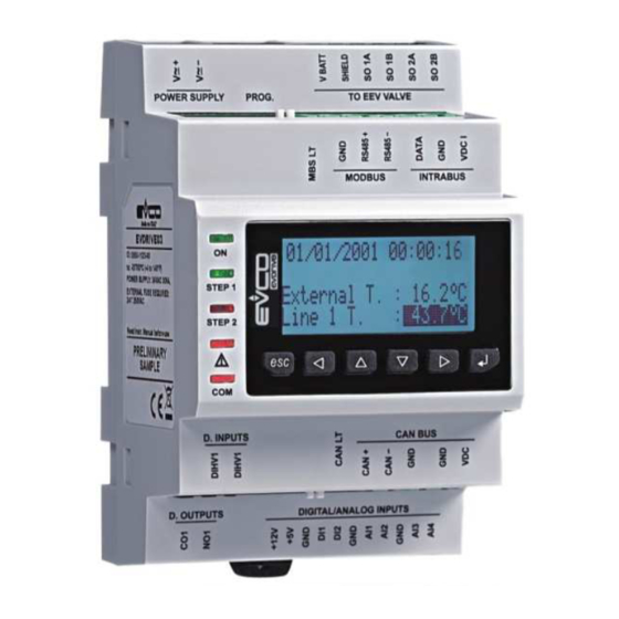
Page 8: Description
EVDRIVE04 | User manual ver. 1.0 | Code 144EPD4I104 DESCRIPTION Description The following drawing shows the aspect of EVDRIVE04. The following table shows the meaning of the parts of EVDRIVE04. Part Meaning digital output analog inputs and free of voltage digital inputs... -
Page 9: Size And Installation
EVCO S.p.A. EVDRIVE04 | User manual ver. 1.0 | Code 144EPD4I104 SIZE AND INSTALLATION Size The following drawing shows the size of EVDRIVE04 (4 DIN modules); size in mm (in). Page 9 of 78... -
Page 10: Installation
EVCO S.p.A. EVDRIVE04 | User manual ver. 1.0 | Code 144EPD4I104 Installation On DIN rail 35.0 x 7.5 mm (1.377 x 0.295 in) or 35.0 x 15.0 mm (1.377 x 0.590 in). To install the device operate as shown in the following drawing. -
Page 11: Electrical Connection
EVCO S.p.A. EVDRIVE04 | User manual ver. 1.0 | Code 144EPD4I104 ELECTRICAL CONNECTION Meaning of the connectors The following drawing shows the connectors of EVDRIVE04. The following tables show the meaning of the connectors; for further information look at chapter 11 “TECHNICAL DATA”. - Page 12 EVCO S.p.A. EVDRIVE04 | User manual ver. 1.0 | Code 144EPD4I104 common analog inputs and free of voltage digital inputs analog input 1 (which can be set via configuration parameter for NTC/Pt 1000 probes and for 0-20 mA/4-20 mA) analog input 2 (which can be set via configuration parameter for NTC/Pt 1000 probes and for...
- Page 13 SO 2A bipolar stepper motor coil 2 SO 2B bipolar stepper motor coil 2 With reference to the previous table, the following one shows how to connect to EVDRIVE04 the most common electronic expansion valves Sporlan and Alco. Wire (color) Terminal...
- Page 14 EVCO S.p.A. EVDRIVE04 | User manual ver. 1.0 | Code 144EPD4I104 Power supply Terminal Meaning power supply device (not isolated; 24 VAC +10% -15%, 50/60 Hz ±3 Hz, 40 VA max. or V≅+ 24... 37 VDC, 22 W max.) power supply device (not isolated; 24 VAC +10% -15%, 50/60 Hz ±3 Hz, 40 VA max. or V≅-...
-
Page 15: Example Of Electrical Connection
The following drawing shows an example of electrical connection of EVDRIVE04. Please note the power supply of EVDRIVE04 and that of EPS4B are not isolated one another: it is important to wire correctly the devices as indicated in the drawing. -
Page 16: Additional Information For Electrical Connection
11 “TECHNICAL DATA” disconnect the power supply of the device before servicing it do not use the device as safety device for the repairs and for information about the device please contact the EVCO sales network. Page 16 of 78... -
Page 17: User Interface
USER INTERFACE Preliminary information EVDRIVE04 is available in built-in and blind version (according to the model). The built-in versions can be programmed through the user interface, the blind ones must be used with a remote user interface (for example EPJgraph): both the versions can be programmed through the set-up software system Parameters Manager;... - Page 18 EVCO S.p.A. EVDRIVE04 | User manual ver. 1.0 | Code 144EPD4I104 LED auxiliary if parameter Ph80 = 0, LED status if it is lit, the device will be working in superheating algorithm modality if it flashes slowly, the device will be working in manual or in debugger modality...
-
Page 19: Operation
EVCO S.p.A. EVDRIVE04 | User manual ver. 1.0 | Code 144EPD4I104 OPERATION Switch on and resynchronization At switch-on and after a resynchronization, the fundamental parameters for moving the motor are acquired. The parameters of pressure and temperature units of measure are loaded at switch-on, and, if necessary, is performed the conversion of all the parameters of pressure and temperature. -
Page 20: Valve Selection
EVCO S.p.A. EVDRIVE04 | User manual ver. 1.0 | Code 144EPD4I104 6.1.2 Valve selection To select the desired valve, it is necessary to set the correct value in Valve selection (parameter Pi07). Setting this parameter to a value of 0 (generic valve) means setting the parameters Pr50 to Pr55 is required, with which it is possible to specify the value of each valve parameter. -
Page 21: Operation
EVCO S.p.A. EVDRIVE04 | User manual ver. 1.0 | Code 144EPD4I104 It means if the nominal step rate of the valve is higher than 625 steps/s, 8 microsteps/s will be used; while if the nominal step rate is lower than 625 steps/s, 16 microsteps/s will be used. -
Page 22: Operating Mode
6.2.1 Preliminary information EVDRIVE04 implements a stepper motor control according to the state machine presented in the table here below (hereinafter the document will make reference to these status). The state in which the algorithm is in may be readable in the FSM status (Finite State Machine, parameter Stat). -
Page 23: Stand-By And Operation Mode Selection
EVDRIVE04. Selecting values from 6 to 9, it is possible to operate the EVDRIVE04 in standalone mode if a communications fault occurs, in this case the DI1 or DI2 inputs must be configured as enable (parameter Ph11 = 1 or Ph21 = 1). -
Page 24: Analog Inputs
EVCO S.p.A. EVDRIVE04 | User manual ver. 1.0 | Code 144EPD4I104 Analog inputs The configuration of each analog inputs is achieved by setting the related parameter: Aix probe type (Piax) determines the kind of probe connected to the analog input and Aix probe usage (Piux) determines the use of the analog input, where "x"... -
Page 25: Analog Positioner Control
EVCO S.p.A. EVDRIVE04 | User manual ver. 1.0 | Code 144EPD4I104 In this example, the following values have been applied to the AI4 probe: PH60 = 0 (pressure measurement unit = Bar) P4Xty = 1 (0÷20 mA) PxYty = 1 (BarA) -
Page 26: Algorithm Start-Up
EVCO S.p.A. EVDRIVE04 | User manual ver. 1.0 | Code 144EPD4I104 Algorithm start-up To enter algorithm mode, from the Stand-by off (10), set the Main control type parameter Pr01 = 6 to perform Superheat (SH) control or Pr01 = 8 to perform hot gas bypass control. If all the configuration is correct enter in Stand-by on (11) and then in the Stabilization (40), in which is performed a positioning to Stabilization position (parameter Pr09) and await Stabilization delay (parameter Pr08). -
Page 27: Debugging Mode
EVCO S.p.A. EVDRIVE04 | User manual ver. 1.0 | Code 144EPD4I104 Debugging mode The debugger feature is enabled when Pr02 = 2: the valve will move from a Debug minimum position (parameter Prd1) to a Debug maximum position (parameter Prd2) with the step rate defined by Debug step rate (parameter Prd0). - Page 28 EVCO S.p.A. EVDRIVE04 | User manual ver. 1.0 | Code 144EPD4I104 SH parameters set selection (SetP) supports switching from one control parameter set to another simply and quickly. It is possible to change the regulation parameter sets directly by modifying SH parameters set selection (Pr04), if a serial interface is present, or via correctly configured digital inputs on the standalone version.
-
Page 29: Hot Gas Bypass Algorithm
EVCO S.p.A. EVDRIVE04 | User manual ver. 1.0 | Code 144EPD4I104 6.10.2 Hot gas bypass algorithm The purpose of this control is to maintain the temperature at its set-point value. After selecting the control algorithm, it is necessary to set the various regulation parameters:... -
Page 30: Alarm Relay
EVCO S.p.A. EVDRIVE04 | User manual ver. 1.0 | Code 144EPD4I104 6.11 Alarm relay The alarm relay is managed directly by the application. It is possible to set the Relay function (parameter Ph01) and Relay logic (parameter Ph02). The alarm relay can be operate if there is an alarm situation depending of the choose (Ph01 = 1÷5): any alarm, only probe alarm, only LoSH alarm, only for MOP alarm, only for valve alarm. -
Page 31: Configuration
EVCO S.p.A. EVDRIVE04 | User manual ver. 1.0 | Code 144EPD4I104 CONFIGURATION Unit of measurements Units of measurement used in the internal algorithm are Celsius (ºC) and Kelvin (K) degrees in tenths for temperatures, and barG in hundreds for pressure. -
Page 32: User Menu
EVCO S.p.A. EVDRIVE04 | User manual ver. 1.0 | Code 144EPD4I104 7.2.1 User menu Make sure the power supply is switched on. Move among the pages using the buttons as shown in the example here below, using the buttons to scroll through the menu pages: Page User.1... -
Page 33: Installer Menu
EVDRIVE04 | User manual ver. 1.0 | Code 144EPD4I104 The first pages are dedicated to the end user and permit display of major features of the EVDRIVE04, any alarm messages, or whether it is necessary to resynchronise or reset the machine after changing parameters. In the PageUser2 , the fourth line is visible and blinking only if there is a request for resynchronization;... - Page 34 The backup and restore functionalities are active only in Stand-by off (10). They are protected by the Level 5 password and permit to download a copy of the EVDRIVE04 application's parameters and/or the driver's parameters (communication settings, etc.) in the memory or in the parameters key.
-
Page 35: Configuring A Blind Version
EVCO S.p.A. EVDRIVE04 | User manual ver. 1.0 | Code 144EPD4I104 Configuring a blind version The following procedures show an example of configuration of a blind version through an user interface (in the example EPJgraph) and through its user interface. -
Page 36: Main Menu
EVCO S.p.A. EVDRIVE04 | User manual ver. 1.0 | Code 144EPD4I104 Main menu The following procedures show how to gain access to the main menu. The main menu provides information on the project, on the status of the inputs, allows to set the level’s passwords, etc. -
Page 37: Connecting The Device Through The Set-Up Software System Parameters Manager
EVCO S.p.A. EVDRIVE04 | User manual ver. 1.0 | Code 144EPD4I104 CAN network configuration and status pages Modbus on RS485 configuration page USB status page Password setting page Diagnostic page Internal status RS485 status Connecting the device through the set-up software system Parameters Manager The following procedure shows how to connect the device to the set-up software system Parameters Manager. -
Page 38: Backup And Restore
Backup and restore If the EVDRIVE04 driver version is displayed (using the built-in display or another display connected via the CAN port) you can view the backup / restore pages which permit to save a copy of the memory areas of the parameters. The copy can be done in another area of the memory or in an external memory (parameters key) connected to the communication programming port. -
Page 39: Reprogramming
EVCO S.p.A. EVDRIVE04 | User manual ver. 1.0 | Code 144EPD4I104 Reprogramming It is possible to reprogram the device using a USB pen in which the work.ucjb and work.ucje files have been copied. Once the USB pen is inserted, the files are copied in the device, which restarts: if the downloaded program is suitable, the device is reprogrammed with the new version. -
Page 40: Simulation Mode
EVDRIVE04 | User manual ver. 1.0 | Code 144EPD4I104 Simulation mode EVDRIVE04 can be used in input simulation mode by setting the following parameters. The value of Probe 1/2/3/4 Simulation value (Si5/6/7/8) is in accordance with its configuration: tenths of a degree if configured as a temperature probe... -
Page 41: List Of Configuration Parameters
EVCO S.p.A. EVDRIVE04 | User manual ver. 1.0 | Code 144EPD4I104 List of configuration parameters The following is a complete list of parameters managed by the application, each with a short code, the ModBus address (Adr), brief description, default values and limits, measurement units (U), the menu in which they are accessed (M) and the notes. - Page 42 EVCO S.p.A. EVDRIVE04 | User manual ver. 1.0 | Code 144EPD4I104 = from CAN bus = reserved = from serial Modbus RS-485 = from serial Modbus USB = from CAN bus + DI1/2 in communication error = reserved = from serial Modbus RS-485 + DI1/2 in comm.
- Page 43 EVCO S.p.A. EVDRIVE04 | User manual ver. 1.0 | Code 144EPD4I104 Par. Add. Acc. Min. Mas. Unità Default Menu Valve and driver: debug Prd0 1616 1000 step/s User debug step rate Prd1 1617 0.00 Prd2 0.00 User debug minimum position...
- Page 44 EVCO S.p.A. EVDRIVE04 | User manual ver. 1.0 | Code 144EPD4I104 Pa02 1571 Installer communication alarm delay enable LoSH alarm Pa10 1572 - - - - Installer = yes Pa11 1573 25.0 Installer LoSH alarm hysteresis Pa12 1574 Installer LoSH alarm delay...
- Page 45 EVCO S.p.A. EVDRIVE04 | User manual ver. 1.0 | Code 144EPD4I104 Valve driver: refrigerant Par. Add. Acc. Min. Mas. Unità Default Menu equipment type of refrigerant = R-22 = R-134A = R-402A = R-404A = R-407A = R-407C = R-410A...
- Page 46 EVCO S.p.A. EVDRIVE04 | User manual ver. 1.0 | Code 144EPD4I104 = Sporlan SEH 100 = Sporlan SEHI 175/400 10 = Sporlan SDR-3 11 = Sporlan SDR-4 12 = Sporlan ESX UNI 13 = Sporlan EDEV B/C UNI 20 = Castel 261...
- Page 47 EVCO S.p.A. EVDRIVE04 | User manual ver. 1.0 | Code 144EPD4I104 = backup battery status free of voltage digital input DI2 logic Ph20 1624 - - - - Manufact. = normally open = normally closed free of voltage digital input DI2 function...
- Page 48 EVCO S.p.A. EVDRIVE04 | User manual ver. 1.0 | Code 144EPD4I104 Piu1 = 1 or 2) = NTC probe = Pt 1000 probe 10 = 4÷20 mA transducer (0÷10 Barg) 11 = 4÷20 mA transducer (0÷16 Barg) 12 = 4÷20 mA transducer (0÷30 Barg)
- Page 49 EVCO S.p.A. EVDRIVE04 | User manual ver. 1.0 | Code 144EPD4I104 analog input AI2 probe type (used if Piu2 = 1 or 2) = NTC probe = Pt 1000 probe 10 = 4÷20 mA transducer (0÷10 Barg) 11 = 4÷20 mA transducer (0÷16 Barg)
- Page 50 EVCO S.p.A. EVDRIVE04 | User manual ver. 1.0 | Code 144EPD4I104 Probe settings: analog input AI3 Par. Add. Acc. Min. Mas. Unità Default Menu analog input AI3 function Piu3 1662 - - - - Manufact. = suction temperature probe analog input AI3 probe type...
- Page 51 EVCO S.p.A. EVDRIVE04 | User manual ver. 1.0 | Code 144EPD4I104 = barG = barA P4YM 1676 P4Ym 300.00 barG/barA 1.00 Manufact. Y max value P4Ym 1677 P4YM barG/barA 0.00 Manufact. Y min value 300.00 Par. Add. Acc. Min. Mas.
- Page 52 EVCO S.p.A. EVDRIVE04 | User manual ver. 1.0 | Code 144EPD4I104 Probe 1 Simulation value tenths of a degree if configured as a Ps05 1706 32767 User temperature probe 32768 hundredths of mA if configured as a current probe Probe 2 Simulation value...
- Page 53 EVCO S.p.A. EVDRIVE04 | User manual ver. 1.0 | Code 144EPD4I104 internal unit of measure 0: pressure in bar 1: pressure in psi 0: temperature in °C/K 1645 - - - - - - - - - - - -...
- Page 54 EVCO S.p.A. EVDRIVE04 | User manual ver. 1.0 | Code 144EPD4I104 LoSH algorithm is running LoSH alarm HiSH algorithm is running HiSH alarm LOP algorithm is running LOP alarm MOP algorithm is running b10: MOP alarm b11: b12: LP alarm...
- Page 55 EVCO S.p.A. EVDRIVE04 | User manual ver. 1.0 | Code 144EPD4I104 1799 0.00 100.00 - - - - User target position enable valve status EnaS 1800 - - - - - - - - User = valve not enabled = valve enabled...
- Page 56 EVCO S.p.A. EVDRIVE04 | User manual ver. 1.0 | Code 144EPD4I104 0: AI1 0: AI2 0: AI3 0: AI4 255 = no probe Pe backup probe 0: AI1 0: AI2 PePrB 1818 - - - - - - - -...
-
Page 57: Serial Communication
See the “Enable EVDRIVE04” section. The EVDRIVE04 behaves as an expansion to read the analog inputs AI1 and AI2, read digital inputs and write the relay. (Note that driving the relay by the controller completely bypasses its function set by parameter.) CANBUS serial communication The EVCO controllers primarily use a protocol based on CANbus for communication with controllable systems. - Page 58 EVCO S.p.A. EVDRIVE04 | User manual ver. 1.0 | Code 144EPD4I104 Target position (Psp) FW project Current valve position % (PAtt) FW variation Communication alarm enable status(Pa01) FW version Communication alarm delay (Pa02) FW revision 8.2.1.2 Control variables AI1 type (AI1T used if Piu1 = 0)
-
Page 59: Commands
EVCO S.p.A. EVDRIVE04 | User manual ver. 4.0 | Code 144EPDE404 8.2.2 Commands For the variables that need an immediate refresh, commands are implemented. The CommandOut allows to write commands on the device. The device performs the new values as soon as possible. -
Page 60: Alarms And Errors
EVCO S.p.A. EVDRIVE04 | User manual ver. 4.0 | Code 144EPDE404 ALARMS AND ERRORS Alarms and errors The system supports a series of alarms related to both the system (memory, probes, communication, configuration, etc.), and the regulation algorithm (LoSH, HiSH, LOP, MOP, Low Pressure). -
Page 61: Communication Error
EVCO S.p.A. EVDRIVE04 | User manual ver. 4.0 | Code 144EPDE404 Invalid value for parameter PIA3 Invalid value for parameter PIA4 PIu1 configured as another Piux Parameters Piu1, Piu2, Piu3 and Piu4 must each PIu2 configured as another PIux have different values, or null. -
Page 62: Probe Error
EVCO S.p.A. EVDRIVE04 | User manual ver. 4.0 | Code 144EPDE404 The significance of bit 3 and 2 of Alarm status (AlSt) are shown in the following table: bit3 bit2 Significance No communication alarm Warning Communication alarm in standalone mode... -
Page 63: Power Failure And Backup Battery Error
EVDRIVE04 | User manual ver. 4.0 | Code 144EPDE404 Power failure and backup battery error The EVDRIVE04 supports connection to a backup battery in order to allow a complete closure of the valve in the case of power supply failure. -
Page 64: Superheat Algorithm Protection Functions
EVCO S.p.A. EVDRIVE04 | User manual ver. 4.0 | Code 144EPDE404 Superheat algorithm protection functions 9.8.1 LoSH When enabled (Pa10), this alarm is triggered when the SH drops below the low heating threshold (Pc02, Pp02, Pd02). The condition is signalled in the Algorithm status (AlgS) and, when the timeout (Pa12) expires, an alarm is set. -
Page 65: Parameters Error
Ph61. If this alarm occurs, the user should check and correct all the parameters of temperature and pressure, cancel the alarm leading to 1 bit 0 of the variable Command (Cmd), and then reset the EVDRIVE04. page 65 of 78... -
Page 66: Accessories
EVCO S.p.A. EVDRIVE04 | User manual ver. 4.0 | Code 144EPDE404 ACCESSORIES 10.1 optoisolated RS-485/USB serial interface EVIF20SUXI 10.1.1 Introduction EVIF20SUXI is a non optoisolated RS-485/USB serial interface. Through the interface it is possible to connect the driver to the set-up software system Parameters Manager. -
Page 67: Size
EVCO S.p.A. EVDRIVE04 | User manual ver. 4.0 | Code 144EPDE404 10.1.3 Size Size is in mm (in). 10.1.4 Connection to the Personal Computer Operate as follows: Connect the RS-485 port on screw terminal block of the interface to the RS-485 port of the device using three... -
Page 68: Backup Module Eps4B
EVCO S.p.A. EVDRIVE04 | User manual ver. 4.0 | Code 144EPDE404 10.2 Backup module EPS4B 10.2.1 Introduction EPS4B is a backup module. Through the module it is possible to close the valve in case of lack of power supply of the driver. -
Page 69: Size
Connection to the device Look at chapter 4 “ELECTRICAL CONNECTION”Operate as follows: Please note the power supply of EVDRIVE04 and that of EPS4B are not isolated: it is important to wire correctly the devices as indicated in chapter 4. page 69 of 78... -
Page 70: Technical Data
EVCO S.p.A. EVDRIVE04 | User manual ver. 4.0 | Code 144EPDE404 TECHNICAL DATA 11.1 Technical data Purpose of the device: electronic expansion valves driver. Box: self-extinguishing grey. 71.0 x 128.0 x 60.0 mm (2.795 x 5.039 x 2.362 in; W x H x D);... - Page 71 EVCO S.p.A. EVDRIVE04 | User manual ver. 4.0 | Code 144EPDE404 The maximum lengths of the connecting cables are the following: power supply device: 30 m (98 ft) analog inputs: 100 m (328 ft) power supply 0-20 mA/4-20 mA/0-5 V ratiometric/0-10 V...
- Page 72 EVCO S.p.A. EVDRIVE04 | User manual ver. 4.0 | Code 144EPDE404 4 inputs of which 2 inputs (non optoisolated, which can be set via configuration parameter for NTC/Pt 1000 probes and for 0-20 mA/4-20 mA/0-5 V ratiometric transducers) which can be set via...
- Page 73 EVCO S.p.A. EVDRIVE04 | User manual ver. 4.0 | Code 144EPDE404 0-5 V ratiometric analog inputs Input resistance: ≥ to 10K Ω. Accuracy: ±1% of the full scale. Resolution: 0.01 V. Conversion time: 100 ms. Protection: against the reversal of polarity.
- Page 74 EVCO S.p.A. EVDRIVE04 | User manual ver. 4.0 | Code 144EPDE404 128 x 64 pixel single colour (black with rearlighting through white signalling LEDs. LEDs) graphic display, signalling LEDs. 1 SPST 5 res. A @ 250 VAC (5 res. A @ 30 VDC) output (electromechanical relay) which can be set via configuration parameter as alarm output/solenoid valve/resynchronization valve.
- Page 75 EVCO S.p.A. EVDRIVE04 | User manual ver. 4.0 | Code 144EPDE404 1 non optoisolated CAN port optoisolated with CANBUS communication CAN port with protocol, optoisolated 1 USB port. CANBUS RS-485 port with MODBUS communication communication protocol and 1 protocol and 1 USB port.
- Page 76 EVCO S.p.A. EVDRIVE04 | User manual ver. 4.0 | Code 144EPDE404 page 76 of 78...
- Page 77 This document is exclusive property of EVCO; reproduction and disclosure are prohibited without express authorisation from EVCO. EVCO is not liable for any features, technical data and possible errors stated in this document or deriving from use of the same.
- Page 78 EVCO S.p.A. EVDRIVE04 | User manual ver. 4.0 | Code 144EPDE404 EVCO S.p.A. Via Feltre 81, 32036 Sedico (BL) ITALY phone +39 0437 8422 | fax +39 0437 83648 email info@evco.it | web www.evco.it page 78 of 78...
Need help?
Do you have a question about the EVDRIVE04 and is the answer not in the manual?
Questions and answers