Table of Contents
Advertisement
Quick Links
Advertisement
Table of Contents

Related Manuals for Tekron TTM 01-G


Summary of Contents for Tekron TTM 01-G
- Page 1 TTM 01-G USER MANUAL...
-
Page 2: Table Of Contents
Location ................................11 Power Supply ............................... 11 Hazardous Voltage .............................. 12 Earthing ................................12 Mounting the TTM 01-G ............................13 Connecting the TTM 01-G ........................... 13 Factory Reset ..............................15 Factory Hardware Options ..........................16 Power Supply Options ............................16 Optional Output Cards ............................ - Page 3 String-E Time Code O/P ..........................26 String-F Time Code O/P ..........................27 String-G Time Code O/P ..........................28 NMEA ZDA Time Code O/P .......................... 29 NMEA RMC Time Code O/P ......................... 31 Warranty ................................. 33 TTM 01-G Manual / October 2018...
-
Page 4: Introduction
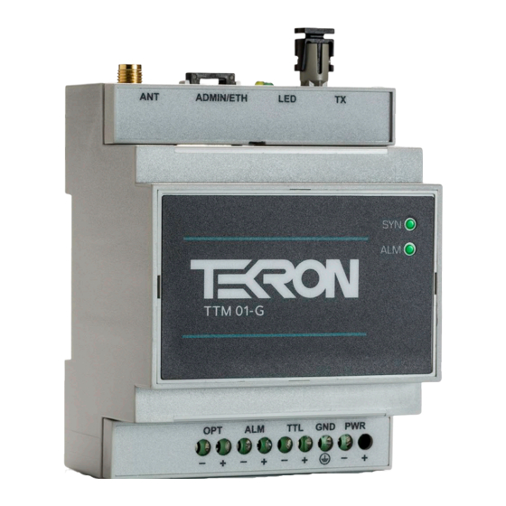
Introduction Welcome to the TTM 01-G user manual! This document contains everything you need to know about the key features, hardware, and installation process of the TTM 01-G. Product Overview The TTM 01-G is a powerful and cost-effective synchronization solution for Remote Terminal Units (RTUs), Protection Relays and other Intelligent Electronic Devices used in electrical sub-stations and industrial control installations. -
Page 5: Led Indicators
LED Indicators The top of the TTM 01-G features two LED indicators. The SYN LED shows synchronization status, while the ALM LED shows the alarm status of the unit. Outputs are synchronized to UTC time only when the SYN LED is fully illuminated. - Page 6 This alarm comes up when the DHCP server is unavailable or when the IP address is assigned Address Fault to some other node in the network and cannot be assigned to the TTM 01-G Ethernet port. Under such situations the Ethernet port defaults to a link local address.
-
Page 7: Inputs And Outputs
SMA male connector center pin is straight before plugging in. Antenna Cable Considerations The TTM 01-G antenna port expects a signal with a gain of at least 15 dB, and no more than 35 dB, with 20 – 35 dB being the optimal gain range. -
Page 8: Eth: Ethernet Interface (St Fiber / Rj-45)
ETH: Ethernet Interface (ST Fiber / RJ-45) TTM 01-G units are fitted with either an RJ-45 10/100 Mbps Ethernet interface or an ST multi-mode Fiber 100BASE-FX Ethernet interface. The unit can be configured over the LAN (Local Area Network) and can be loaded with PTP or NTP / SNTP Licenses. -
Page 9: Alm: Alarm Output
The TTM 01-G operates with the alarm relays energized during normal operation, and de-energized in the alarm state. It follows that, in the event of all power to the TTM 01-G being lost, the alarm relay defaults to the “alarm”... -
Page 10: Software
Software Configuration Tool The TTM 01-G can be configured via Ethernet. The configuration tool can be downloaded from the Tekron Support website: www.support.tekon.com. By default, the unit is shipped with DHCP enabled for automatic IP address assignment, with a fall back to link local addressing (169.254.xxx.xxx) if no DHCP server is present. -
Page 11: Installation
Installation Identification Each TTM 01-G unit is shipped with an identification label on the side of the case. The label provides details of the optional output (if any), the power supply fitted to the unit, and the unit’s serial number. -
Page 12: Hazardous Voltage
Figure 5). This must be connected to earth for full protection of the TTM 01-G. Figure 5 - GND screw clamp The unit must be safety earthed whenever it is powered on, using the earth terminal as pictured in Figure 5 . -
Page 13: Mounting The Ttm 01-G
Mounting the TTM 01-G The TTM 01-G is designed to be mounted to a standard 'Top Hat' din rail mount using the supplied clips on the base (see Figure 6). The clips can also be used to screw mount the unit by extending them beyond the case edge. - Page 14 Figure 7 – TTM 01-G Top Connectors (left) and Bottom Connectors (right) TTM 01-G Manual / October 2018...
-
Page 15: Factory Reset
Factory Reset The TTM 01-G features the ability to reset to factory default settings in the event that the administrator password is forgotten, or if the time server is rendered unreachable on the network due to incorrect settings, provided that physical access to the unit is available. -
Page 16: Factory Hardware Options
Optional Output Cards The TTM 01-G has a slot for one I/O card, to allow a variety of user interfaces. Each card is limited to one additional port with at least 3 kV isolation from the rest of the system to avoid current loops. -
Page 17: Isolation And Protection
The power supply isolation varies from 1.6 kV for low and medium voltage power supplies to 3 kV for the high voltage power supply. In addition, isolation protects the internal electronics from longitudinal transient voltages and transient suppression devices protect from transverse transient voltages. TTM 01-G Manual / October 2018... -
Page 18: Lightning Protection
A lightning protection kit should be fitted into the antenna lead-in cable if lightning strikes are a risk in the location of installation. The Tekron supplied antenna kit can be ordered with a lightning arrestor, two coaxial cable connectors, a connector crimp tool, and mounting hardware. -
Page 19: Appendix
2 Pin + common earth Power drain 4 W max Fiber transmitter is compatible with 50/125 µm, 62.5/125 µm and 100/140 µm multimode glass fiber. Fiber Ethernet is compatible with 50/125 µm and 62.5/125 µm multimode glass fiber. TTM 01-G Manual / October 2018... -
Page 20: Serial Output String (Serial Output Option)
Time mode: ”0” = Local time, “1” = UTC time <CR> Carriage Return: HEX 0D <LF> Line Feed: HEX 0A Table 7 - NGTS String Time Code Format Fields Example: Interpretation: T020422112340<CR><LF> Monday 22 April 2002 – 12:34 local time TTM 01-G Manual / October 2018... -
Page 21: Irig J-17 Time Code O/P
“00” – “2” HEX 3A Seconds: “00” – “59” <CR> Carriage Return: HEX 0D <LF> Line Feed: HEX 0A Table 8 - IRIG-J17 String Time Code Format Fields Example: Interpretation: <SOH>112:12:34:36<CR><LF> day 112, time 12:34:36 TTM 01-G Manual / October 2018... -
Page 22: String-A Time Code O/P
“00” – “99” representing the last two digits of the year since 2000 <CR> Carriage Return: HEX 0D <LF> Line Feed: HEX 0A Table 9 - String A Time Code Format Fields Example: Interpretation: <SOH>112:12:34:36:10<CR><LF> day 112, time 12:34:36, year (20)10 TTM 01-G Manual / October 2018... -
Page 23: String-B Time Code O/P
Clock is accurate to 100 µs ‘?’ Clock accuracy may be worse than 100 µs Table 11 - String B Quality Character 'Q' Indicators Example: Interpretation: <SOH>112:12:34:36?<CR><LF> day 112, time: 12:34:36, >100 µs sync error TTM 01-G Manual / October 2018... -
Page 24: String-C Time Code O/P
HEX 20 (space) <SPACE> HEX 20 (space) <SPACE> HEX 20 (space) Table 12 - String C Time Code Format Fields Example: Interpretation: <CR><LF>? 02 112 12:34:36.000 day 112 of year (20)02, time: 12:34:36, out-of-sync TTM 01-G Manual / October 2018... -
Page 25: String-D Time Code O/P
String-D is IDENTICAL in content to String-B (in Table 10), but the second mark is at the leading edge of the start- bit of the (<CR>). Example: Interpretation: <SOH>112:12:34:36?<CR><LF> day 112, time: 12:34:36, >100 µs sync error TTM 01-G Manual / October 2018... -
Page 26: String-E Time Code O/P
Quality character, as defined in String B (refer to Table 11) <CR> Carriage Return: HEX 0D <LF> Line Feed: HEX 0A Table 13 - String-E Time Code Format Fields Example: Interpretation: <SOH>2004:112:12:34:36?<CR><LF> 2004, day 112, 12:34:36pm, >100us sync error TTM 01-G Manual / October 2018... -
Page 27: String-F Time Code O/P
<CR> Carriage Return: HEX 0D <LF> Line Feed: HEX 0A <BEL> HEX 07 Table 14 - String-F Time Code Format Fields Example: <CR><LF>1100<CR><LF>44132530<CR><LF>54138<CR><LF><CR><LF>45012530<CR><LF>55138<CR><LF><BEL> Interpretation: Local time: 1:25:30pm, day 138. UTC time: 1:25:30am, day 138. TTM 01-G Manual / October 2018... -
Page 28: String-G Time Code O/P
Time/date invalid – clock is out of sync Hold-over mode – running on local Oscillator GPS / IRIGB controlled mode GPS / IRIGB controlled mode (high accuracy) Table 16 - String-G Clock Status Indicators TTM 01-G Manual / October 2018... -
Page 29: Nmea Zda Time Code O/P
Local time zone offset sign (positive means local time leads UTC) ASCII “,” (comma) Local time zone offset from UTC in hours ASCII “,” (comma) Local time zone offset from UTC in minutes ASCII “*” TTM 01-G Manual / October 2018... - Page 30 <CR> Carriage Return: HEX 0D <LF> Line Feed: HEX 0A Table 18 - NMEA-ZDA Time Code Format Fields Example: Interpretation: $GPZDA,123456.0023042010+1200* UTC time is 12:34:56, 23 April 2010, the local time offset is +12:00 TTM 01-G Manual / October 2018...
-
Page 31: Nmea Rmc Time Code O/P
2-digit hex representation of the result of XORing the 8 data bits of each character between, but not including the "$" and "*". <CR> Carriage Return: HEX 0D <LF> Line Feed: HEX 0A Table 19 - NMEA-RMC Time Code Format Fields TTM 01-G Manual / October 2018... - Page 32 Example: $GPRMC,102520.00,A,8530.1383,N,12847.8675,E,0.0,0.0,230223,0.0,E*01<CR><LF > Interpretation: UTC Time: 10:25:20. valid. Latitude: 85°, 39.1383 minutes, North. Longitude: 128°, 47.8675 minutes, East. Date: of February 2023. TTM 01-G Manual / October 2018...
-
Page 33: Warranty
NT, Windows XP, Windows Vista, Windows 7, Windows 8 and Windows 10 are trademarks of Microsoft™ Corp. Copyright ©2018 Tekron International Ltd. All rights reserved. No part of the contents of this document may be transmitted or reproduced in any form or by any means without the written permission of Tekron International Ltd.
Need help?
Do you have a question about the TTM 01-G and is the answer not in the manual?
Questions and answers