Table of Contents
Advertisement
Advertisement
Table of Contents

Related Manuals for Tekron PTP TRANSLATOR


Summary of Contents for Tekron PTP TRANSLATOR
- Page 1 PTP TRANSLATOR USER MANUAL...
-
Page 2: Table Of Contents
Power Supply Options ........................................4 Isolation & Protection ........................................4 Installation .............................................. 5 Identification ............................................... 5 Mounting the PTP Translator ......................................5 Connecting the PTP Translator ....................................... 5 Product Configuration ........................................6 Appendix ..............................................7 PTP Translator Specifications ......................................7 Serial Output String (Serial Output Option) ................................ -
Page 3: Introduction
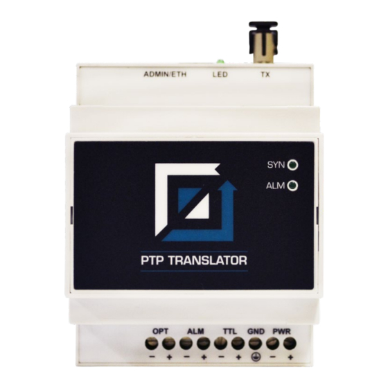
Figure 1 – PTP Translator Front View 2 LED Indicators The top of the PTP Translator features two LED indicators. The SYN LED shows synchronization status of the internal PTP decoder, while the ALM LED shows the alarm status of the unit. -
Page 4: Inputs And Outputs
OPT: Optional Output The PTP Translator has a slot for one IO card to allow a variety of user interfaces. Each card is limited to one additional port with at least 3 kV isolation from the rest of the system to avoid current loops. -
Page 5: Installation
Mounting the PTP Translator The PTP Translator is designed to be mounted to a standard din rail mount using the supplied clips on the base (See Figure 2). The clips can also be used to screw mount the unit by extending them beyond the case edge. -
Page 6: Product Configuration
Note: The Power supply has polarity protection built in to prevent damage. The label on the side of PTP Translator indicates the type of IO card: Do not apply voltages to output only cards and ensure that switch cards are connected appropriately! -
Page 7: Appendix
Note the UTC accuracy depends on the PTP interface and the accuracy of the clock supplying the master time signal. Fibre transmitter is compatible with 50/125 µm, 62.5/125 µm and 100/140 µm multimode glass fiber. Fibre Ethernet is compatible with 50/125 µm and 62.5/125 µm multimode glass fiber. PTP Translator Manual / December 2014... -
Page 8: Serial Output String (Serial Output Option)
9600 bps, 7-bit ASCII, odd parity Definition <SOH>ddd:hh:mm:ss<CR><LF> Placeholder Content Day of year: range “001” – “366” HEX 3A hour: “00” – ”23” minute: “00” – “2 Seconds: “00” – “59” Example Interpretation: <SOH>112:12:34:36<CR><LF> day 112, time 12:34:36 PTP Translator Manual / December 2014... - Page 9 <CR><LF>Q yy ddd hh mm ss.000 Placeholder Content Quality indicator: ‘ ‘ = in-sync, ‘?’ = out-of-sync HEX 20 (space) Year: “00” – “99” representing the last two digits of the year Day of year: range “001” – “366” PTP Translator Manual / December 2014...
- Page 10 Local hour of day: “00” – ”23” Local minute of day: “00” – “60” seconds: “00” – “59” ASCII “54” (means local day of year follows) Local day of year: “001” – “365” ASCII “45” (means UTC time follows) PTP Translator Manual / December 2014...
- Page 11 The w “Day of Week” is an ASCII character in the range 1-7, 9, A-F representing a single hex digit (nibble) Bits Local Time UTC time Monday 0 Tuesday Wednesday 0 Thursday Friday 0 Saturday Sunday Example Interpretation: <STX>E3123456170410<LF><CR><ETX> High Accuracy Mode, DST, Wed, 12:34:56, 17/4/2010 PTP Translator Manual / December 2014...
- Page 12 UTC day of month, month & 2-digit year ASCII “E*” 2-digit hex representation of the result of XORing the 8 data bits of each character between, but not including the "$" and "*". PTP Translator Manual / December 2014...
-
Page 13: Warranty Statement
Windows XP, Windows Vista, and Windows 7 are trademarks of Microsoft™ Corp. Copyright ©2014 Tekron International Ltd. All rights reserved. No part of the contents of this document may be transmitted or reproduced in any form or by any means without the written permission of Tekron International Ltd. Published in New Zealand.
Need help?
Do you have a question about the PTP TRANSLATOR and is the answer not in the manual?
Questions and answers