Table of Contents
Advertisement
Quick Links
Advertisement
Table of Contents

Related Manuals for Wassp WMB-X230


Summary of Contents for Wassp WMB-X230
- Page 1 TRANSDUCER INSTALLATION MANUAL V2.6...
- Page 2 Further documentation and updated specifications and installation manuals can be found wassp.com GENERAL NOTICES WASSP Ltd. reserves the right to change the contents of this manual and any system specifications without notice. Contact WASSP Ltd. regarding copying or reproducing this manual.
-
Page 3: Table Of Contents
Gland nut travel measurement point for steel glands 5.3. Wideband Fairing Transducer 90-190kHz MOUNTING Figure 13. Gland Assembly - Cable Connectors 6 WASSP Wideband Fairing Transducer 90-190kHz Installation Figure 14. DRX with the Transducer Receive Discharge cover label instruction Figure 15. Ceramic Discharge Module 6.1. -
Page 4: Introduction
This must be sized and constructed accurately. The sea chest provides a stable platform for the transducer and must be mounted as horizontal to the vessel’s waterline as possible. A WASSP gland in alloy, plastic or steel are available for the the transducer cable through- hull seal. Thru-Hull Transducer The WASSP Wideband Fairing Transducer 90-190kHz is available with a fairing that can be cut into a suitable shape for the hull of the ship with a dead rise of up to 30 degrees. -
Page 5: 80Khz Transducer 8 Figure
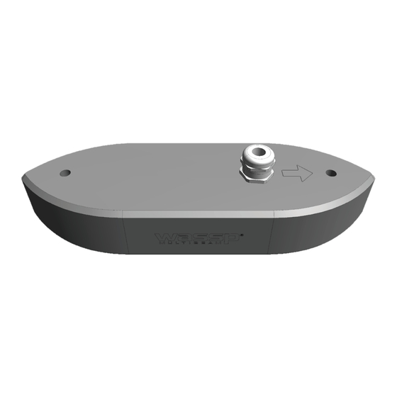
TRANSDUCER INSTALLATION MANUAL TRANSDUCER INSTALLATION MANUAL 2.2. 80KHZ TRANSDUCER 2.3. WIDEBAND FAIRING TRANSDUCER 90-190KHZ Figure 3. Wideband Fairing Transducer 90-190kHz Dimensions Figure 2. 80kHz Transducer Dimensions wassp.com wassp.com Page 8 of 34 Doc: Transducer Installation Doc: Transducer Installation Page 9 of 34 Version: 2.6 May 2021... -
Page 6: Mounting Options
Looking from above (not to scale) Figure 5. Positioning the Transducer on the Vessel Hull CAUTION: The above mounting example is provided as a guide. WASSP Ltd. recommend that a reputable boat builder is used to install the transducer to prevent damage to the vessel’s hull. -
Page 7: Hull Mounting Considerations
V-shaped hulls the housing should be mounted against or close to the keel, again to get the vessel. It must also be mounted so that the flat underside of the transducer is as close deeper and away from aeration and turbulence. The 120 WASSP beam pattern must be to horizontal as possible. -
Page 8: Mounting Assembly
Angle Iron Clamp Optional: 40 x 40 x 5mm mild steel Threaded end Optional: M10 x 1.5 120mm M10 nut Optional wassp.com wassp.com Page 14 of 34 Doc: Transducer Installation Doc: Transducer Installation Page 15 of 34 Version: 2.6 May 2021... -
Page 9: 80Khz Transducer Mounting Assembly
TRANSDUCER INSTALLATION MANUAL TRANSDUCER INSTALLATION MANUAL 5.2. 80KHZ TRANSDUCER MOUNTING ASSEMBLY wassp.com wassp.com Page 16 of 34 Doc: Transducer Installation Doc: Transducer Installation Page 17 of 34 Version: 2.6 May 2021 Version: 2.6 May 2021... -
Page 10: Wideband Fairing Transducer 90-190Khz Mounting
0.05 0.05 0.15 GENERAL TOLERANCES UNLESS OTHERWISE SPECIFIED (COARSE) ≤3 >3-6 >6-30 >30-120 >120-400 >400-1000 >1000-2000 wassp.com wassp.com Page 18 of 34 Doc: Transducer Installation Doc: Transducer Installation Page 19 of 34 Version: 2.6 May 2021 Version: 2.6 May 2021... -
Page 11: Wassp Wideband Fairing Transducer 90-190Khz Installation
CUTTING GUIDE used to guide the fairing over a bandsaw table. » A WASSP gland must be used to lead the WASSP transducer cable through the hull. » Mount the front of the transducer facing forward. (the transducer can be mounted Hold the fairing against the outside of the hull back to front if necessary. -
Page 12: Mounting The Fairing
Place a washer and two nuts on the threaded rods BACKING BLOCK BLOCK, RODS (2) inside the boat to secure the backing block. Take the fairing and backing block off. Mount the WASSP gland step 1 till 6 from chapter 7.2 HULL MARINE SEALANT ON FAIRING, RECESS FAIRING wassp.com... -
Page 13: Transducer Installation
2. Guide the transducer cable trough the WASSP gland. Before guiding the transducer dimensions of the WASSP Ltd. supplied alloy / plastic gland assembly. The steel gland is into place, apply marine sealant between the gland pipe and the transducer cable and different to below. - Page 14 Recheck the gland for leak 6 hours after the boat is in water. Feed the transducer cable through the gland. wassp.com wassp.com Page 26 of 34 Doc: Transducer Installation...
-
Page 15: Transducer Cable
RJ-45 plug wiring is specific to the special preparation is required. WASSP transceiver and does NOT conform to T568A or B: The WASSP transceiver cable end has the RJ-45 connectors RJ-45 Plug Pin fitted with “staggered” cable lengths. This allows each RJ-45 CAT 5 conductor colour... -
Page 16: Cable Connection To Drx
For the 80kHz Transducer, it is important that the receive channels are discharged prior to connection to the DRX. To discharge the transducer use the supplied Ceramic Discharge Module (shipped with WASSP 80kHz Transducers). Figure 15. Ceramic Discharge Module wassp.com wassp.com... -
Page 17: Technical Specification
Table 1. Technical Specification 10 PRODUCT REGISTRATION, SUPPORT AND RESOURCES TECHNICAL SUPPORT If you require maintenance and/or repair contact your local dealer. A list of WASSP dealers and distributors is available at wassp.com. DRX technical support is available directly through: »...
Need help?
Do you have a question about the WMB-X230 and is the answer not in the manual?
Questions and answers