
Related Manuals for DoorHan DSHINF Series


Summary of Contents for DoorHan DSHINF Series
-
Page 1: Table Of Contents
General Information Design Safety Rules Installation Operation Appendix Inflatable dock shelter of DSHINF series Operation and Installation Instructions © DoorHan, 08.2020... -
Page 2: General Information
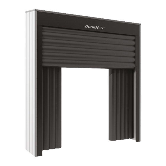
1. GENERAL INFORMATION Dock shelters are designed to ensure tight sealing between loading dock and vehicle bed. 2. DESIGN Fig. 1 1. Top air bag 5. Counterweight 2. Side air bag (left/right) 6. Blower 3. Front storage curtain 7. Dock shelter roof 4. -
Page 3: Safety Rules
3. SAFETY RULES 3.1. SAFETY RULES WHEN WORKING AT HEIGHT Work at height is work in any place located at height of metal chain slings while working around energized wiring 1,3 m from the ground level and carried out from ladders, and equipment! scaffolds, platforms and other devices. -
Page 4: Installation
Installation of dock shelter is restricted to authorized per- The contents of this manual can not be the basis for any sonnel trained at DoorHan training center and having a kind of claim to DoorHan. The manufacturer reserves the corresponding certificate. Use of appropriate mounting right to make any changes to the product construction, tools is strictly required. - Page 5 4.3. PACKAGE INVENTORY Fig. 1 Fig. 2 Fig. 3 Fig. 4 2 pcs Fig. 5 Fig. 6 Fig. 7 Fig. 8 Fig. 9 Fig. 12 Fig. 10 Fig. 11 2 pcs 2 pcs Fig. 13 Fig. 14 Fig. 15 Fig. 16 А...
- Page 6 4.4. INSTALLATION Fig. 1. Prepare side frames View 1 Fig. 1.1. View 1 125 mm ∅ 7 mm Fig. 1.2 Fig. 1.3 А...
-
Page 7: Fig. 2
Fig. 2 View 2 Fig. 2.1. View 2 Fig. 2.2 105 mm А... - Page 8 Fig. 3. Fasten side frames to building wall View 1 View 2 Fig. 3.1. View 1 Fig. 3.2. View 2...
-
Page 9: Fig. 4
Fig. 4 View 2 View 1 Fig. 4.1. View 1 Fig. 4.2 А Fig. 4.4 Fig. 4.3. View 2 А... -
Page 10: Fig. 5.2
Fig. 5 Fig. 5.1 Fig. 5.2 А А Fig. 5.3 А... - Page 11 Fig. 6. Install top air bag Fig. 6.1 Fig. 6.2 А А...
- Page 12 Fig. 7. Install guide rod Fig. 7.1 Fig. 7.2 Fig. 7.3...
-
Page 13: Fig. 8
Fig. 8 820 mm 90° Fig. 9 Fig. 10 А А... - Page 14 Fig. 11 Fig. 12 Before attaching the counterweight cable to the shaft, turn the shaft until the top air bag rises all the way up. Fig. 13. Install counterweight View 1 View 2 Fig. 13.1. View 1 Fig. 13.2. View 2...
- Page 15 Fig. 14. Connect air transfer tubes Fig. 14.1 Fig. 14.2...
- Page 16 Fig. 15 Fig. 15.1 Fig. 15.3 Fig. 15.2 Fig. 15.4 Fig. 15.5...
-
Page 17: Fig. 16
Fig. 16 Fig. 16.1 Fig. 16.2... - Page 18 Fig. 17 Fig. 17.1 Fig. 17.2...
- Page 19 Fig. 18 Fig. 19 Fig. 20 Fig. 21 4,2 32 mm...
- Page 20 5. OPERATION Precautions: Principle of operation: Only qualified personnel acquainted with the design Trailers back into the shelter during loading/unloading and construction of the shelter should handle it. operations while top and side air bags create a tight seal against the truck top and rear body. Prior to operation carefully inspect the dock shelter.
- Page 21 APPENDIX. DRAWINGS Fig. 1. Installation of PVC-buffer...
- Page 22 Fig. 2. Inflatable dock shelter exploded view...
- Page 23 Table 1 to Fig. 2. Spare parts to inflatable dock shelter DSHINF 3,3 3,4 Part number Description DSHINF 3,3 3,4 Inflatable dock shelter Н = 3 300 mm, B = 3 400 mm DSI02.52 Angle unit DSI04.6 Shelter counterbalance 850 100 20 mm DSI02.53 Axial unit DSI04.4...
- Page 24 Table 2 to Fig. 2. Spare parts to inflatable dock shelter DSHINF 3,8 3,6 Part number Description DSHINF 3,8 3,6 Inflatable dock shelter Н = 3 800 mm, B = 3 600 mm DSI02.52 Angle unit DSI02.6 Shelter counterbalance 362 100 40 mm DSI02.53 Axial unit DSI02.4...
- Page 25 Table 3 to Fig. 2. Spare parts to inflatable dock shelter DSHINF 4,9 3,6 Part number Description DSHINF 4,9 3,6 Inflatable dock shelter Н = 4 900 mm, B = 3 600 mm DSI02.52 Angle unit DSI02.6 Shelter counterbalance 362 100 40 mm DSI02.53 Axial unit DSI02.4...
- Page 26 Fig. 3. Dock shelter side frame Table 1 to Fig. 3. Left side frame Part number Description DSI04.1 Left frame assembly 3 260 800 mm DSI05.32 Left side air bag 2 980 800 mm DSI04.11 Left shelter wall assembly 3 260 800 mm DSI02.1 Left frame assembly 3 780 800 mm DSI06.32...
- Page 27 Fig. 4. Top frame exploded view Table 1 to Fig. 4. Top frame with 1 200 mm top air bag Part number Description DSI04.4 Upper dock shelter beam 3 300 1 200 mm (extension 900 mm) DSI04.411 Dock shelter shaft 3110 DSI04.412 Dock shelter plate 3 300 193 mm DSI05.13...
- Page 28 Fig 5. Architectural drawing...
- Page 29 Fig. 6. Blower motor wiring diagram* * If the blower motor is connected to the dock leveler control unit than see a corresponding wiring diagram in the control unit Owner’s Manual.
- Page 32 For information on purchasing, distribution and servicing contact DoorHan central office at: 120 Novaya street bld. 1, Akulovo village, Odintsovo district, Moscow region, 143002, Russia Phone: +7 495 933-24-00 E-mail: info@doorhan.com...
Need help?
Do you have a question about the DSHINF Series and is the answer not in the manual?
Questions and answers