Table of Contents
Advertisement
Quick Links
All manuals and user guides at all-guides.com
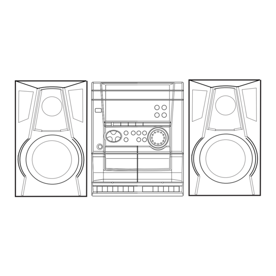
SERVICE MANUAL
COMPACT DISC
STEREO CASSETTE RECEIVER
SYSTEM
NSX–SZ4
NSX–SZ5
NSX–SZ7
• If requiring information about the CD mechanism, see Service Manual of AZG-1,
(S/M Code No. 09-001-335-3NC).
NSX-SZ4
NSX-SZ5
NSX-SZ7
BASIC CD MECHANISM : AZG-1 ZA3RNM
BASIC TAPE MECHANISM : ZZM-2 PR1NM
CD
CASSEIVER
CX–NSZ4
CX-NSZ5
CX-NSZ7
S/M Code No. 09-006-429-1N1
REMOTE
SPEAKER
CONTROLLER
SX–NSZ4
RC–ZAS17
SX–NSZ5
RC–ZAS02
SX–NSZ7
K
K EZ V
EZ
Advertisement
Table of Contents

Related Manuals for Aiwa NSX-SZ4


Summary of Contents for Aiwa NSX-SZ4
- Page 1 All manuals and user guides at all-guides.com NSX-SZ4 NSX-SZ5 K EZ V NSX-SZ7 SERVICE MANUAL BASIC CD MECHANISM : AZG-1 ZA3RNM COMPACT DISC STEREO CASSETTE RECEIVER BASIC TAPE MECHANISM : ZZM-2 PR1NM REMOTE SYSTEM SPEAKER CASSEIVER CONTROLLER NSX–SZ4 CX–NSZ4 SX–NSZ4 RC–ZAS17...
-
Page 2: Specifications
All manuals and user guides at all-guides.com SPECIFICATIONS K MODEL (NSX-SZ4/SZ5) • Design and specifications are subject to change without notice EZ MODEL (NSX-SZ5) • Design and specifications are subject to change without notice... - Page 3 All manuals and user guides at all-guides.com EZ MODEL (NSX-SZ7) • Design and specifications are subject to change without notice V MODEL (NSX-SZ5) • Design and specifications are subject to change without notice...
-
Page 4: Protection Of Eyes From Laser Beam During Servicing
All manuals and user guides at all-guides.com PROTECTION OF EYES FROM LASER BEAM DURING SERVICING This set employs laser. Therefore, be sure to follow carefully the CAUTION instructions below when servicing. Use of controls or adjustments or performance of procedures other than those specified herein may result in hazardous WARNING! radiation exposure. -
Page 5: Note On Before Starting Repair
All manuals and user guides at all-guides.com NOTE ON BEFORE STARTING REPAIR 1. Forced discharge of electrolytic capacitor of power supply block When repair is going to be attempted in the set that uses relay circuit in the power supply block, electric potential is kept charged across the electrolytic capacitors (C101, 102) even though AC power cord is removed. - Page 6 All manuals and user guides at all-guides.com In such a case, check also if the POWER AMPLIFIER circuit or power supply circuit has any abnormalities or not. 2-2. Regarding reset There are cases that the machine does not work correctly because the MICROCOMPUTER is not reset even though the AC power cord is re-inserted, or the software reset (pressing the STOP key + POWER key) is performed.
-
Page 7: Electrical Main Parts List
All manuals and user guides at all-guides.com ELECTRICAL MAIN PARTS LIST REF. NO PART NO. KANRI DESCRIPTION REF. NO PART NO. KANRI DESCRIPTION C104 87-010-545-080 CAP, ELECT 0.22-50V C105 87-010-186-080 CAP,CHIP 4700P 8A-NFA-615-010 C-IC,M38B57MCH-E236FP<EXCEPT 7EZ> C106 87-010-186-080 CAP,CHIP 4700P 8A-NFA-615-010 C-IC,M38B57MCH-E236FP<EXCEPT 7EZ>... - Page 8 All manuals and user guides at all-guides.com REF. NO PART NO. KANRI DESCRIPTION REF. NO PART NO. KANRI DESCRIPTION C605 87-010-179-080 CAP,CHIP S B1200P C869 87-010-197-080 CAP, CHIP 0.01 DM<7EZ> C606 87-010-179-080 CAP,CHIP S B1200P C870 87-010-178-080 CHIP CAP 1000P<7EZ> C609 87-010-213-080 C-CAP,S 0.015-50 B...
- Page 9 All manuals and user guides at all-guides.com REF. NO PART NO. KANRI DESCRIPTION REF. NO PART NO. KANRI DESCRIPTION L941 87-A50-020-010 COIL,ANT LW(COI)<EXCEPT 5V> CN801 87-099-015-010 CONN,13P 6216V L942 87-A50-019-010 COIL,OSC LW(COI)<EXCEPT 5V> FL201 8A-NFA-604-010 FL,10-BT-224GNK L951 8A-NF8-668-010 COIL,AM PACK 2(TOK)<EXCEPT 5V> L101 87-A50-050-010 COIL,CLK 4.19M(COI)<EXCEPT 5V>...
-
Page 10: Transistor Illustration
All manuals and user guides at all-guides.com CHIP RESISTOR PART CODE Chip Resistor Part Coding Figure Resistor Code Value of resistor Chip resistor Dimensions (mm) Symbol Wattage Type Tolerance Resistor Code Form 1/16W 1005 0.35 1/16W 1608 0.45 1/10W 2125 1.25 0.45 1/8W... - Page 11 All manuals and user guides at all-guides.com WIRING-1 (MAIN)
- Page 12 All manuals and user guides at all-guides.com SCHEMATIC DIAGRAM-1 (MAIN 1/2)
- Page 13 All manuals and user guides at all-guides.com SCHEMATIC DIAGRAM-2 (MAIN 2/2)
- Page 14 All manuals and user guides at all-guides.com WIRING-2 (FRONT) VOLUME PLATE EARTH...
- Page 15 All manuals and user guides at all-guides.com SCHEMATIC DIAGRAM-3 (FRONT)
- Page 16 All manuals and user guides at all-guides.com WIRING-3 (PT) SCHEMATIC DIAGRAM-4 (PT) AC 230V 50Hz (CHASSIS)
- Page 17 All manuals and user guides at all-guides.com WIRING-4 (DECK)
- Page 18 All manuals and user guides at all-guides.com FL (10-BT-224GNK) GRID ASSIGNMENT/ANODE CONNECTION GRID ASSIGNMENT...
- Page 19 All manuals and user guides at all-guides.com ANODE CONNECTION...
-
Page 20: Ic Block Diagram
All manuals and user guides at all-guides.com IC BLOCK DIAGRAM IC, LC72131D PHASE DETECTOR CHARGE PUMP POWER REFERENCE UNLOCK DIVIDER DETECTOR RESET SWALLOW COUNTER 1/16, 1/17 4BITS 12BITS PROGRAMMABLE DRIVER UNIVERSAL DATA SHIFT REGISTER LATCH INTERFACE COUNTER 2 3 4 5 6 7 8 9 IC, M62495AFP... - Page 21 All manuals and user guides at all-guides.com IC, LA1844L-A RF. AMP BUFF PILOT DECODER CANCEL ANTI-BIRDIE P-DET STEREO Ø AM/FM LEVEL COMP S-CURVE π PILOT BUFF 304kHz TUNING DRIVE IC, BU1920FS 100kΩ – 8TH SWITCHED CAPACITOR FILTER Vref RCLK QUAR RESET DIFFERENTIAL BI-PHASE...
-
Page 22: Electrical Adjustment
All manuals and user guides at all-guides.com ELECTRICAL ADJUSTMENT A MAIN C.B %$#@098653 1 9 6 L801 TC942 L802 TP4 (DC BAL) L941 IC801 L951 L942 IC301 (DC BAL) (CLK) TP8 (LCH) TP1 (VT) TP9 (RCH) FFE831 DECK–1 R/P/E, DECK-2 P HEAD B FRONT C.B IC101 L101... - Page 23 All manuals and user guides at all-guides.com < TUNER SECTION > < DECK SECTION > 1. Clock Frequency Check 10. Tape Speed Adjustment (DECK 1) Settings: • Test point: TP2 (CLK) Settings: • Test tape: TTA-100 Method: Set to MW 1602kHz and check that the test point •...
- Page 24 All manuals and user guides at all-guides.com IC DESCRIPTION IC, M38B57MCH-E236FP/M38B59MFH-E250FP Pin No. Pin Name Description I-SIG RDS signal level A/D input. (Not used) ___________ I-HOLD Hold voltage level A/D input. I-SW (CD) CD mecha SW A/D input. I-DISH CD turn-table position check A/D input. I-KEY2 KEY2 A/D input.
- Page 25 All manuals and user guides at all-guides.com Pin No. Pin Name Description O-DISH_R CD turn-table reverse turn output. O-DISH_F CD turn-table forward turn output. I-SUBQ Sub code-Q data input. O-CD_CE CD DSP chip enable output. I-WRQ CD WRQ input. O-CLK (CD) CD control clock output .
-
Page 26: Mechanical Parts List
WINDOW,CASS 1<EXCEPT NSZ4 KBM> <EXCEPT NSZ4 KBM> 5 8A-NFA-071-010 WINDOW,CASS 1 BLK<NSZ4 KBM> 27 87-A80-157-010 AC CORD ASSY,E BLK CC 6 87-CE3-023-010 BADGE,AIWA 30N SILV 28 84-ZG1-245-210 CAP,OPTICAL 29 8A-NFB-011-010 CABI,REAR EZSM<NSZ5 EZSM> 7 8A-NFB-001-010 WINDOW,DISP EZ <EXCEPT NSZ4 KBM,NSZ7 EZSM>... - Page 27 All manuals and user guides at all-guides.com MECHANICAL EXPLODED VIEW 1/1 AZG-1 P.C.B ZZM-2 P.C.B HLDR1 PLATE EARTH HLDR2 MECHA P.C.B CHAS, MAIN PLATE EARTH MIC BINDER WIRE...
- Page 28 All manuals and user guides at all-guides.com TAPE MECHANISM EXPLODED VIEW 1/1 TERMINAL,LB1 TERMINAL,LB1...
-
Page 29: Tape Mechanism Parts List
All manuals and user guides at all-guides.com TAPE MECHANISM PARTS LIST 1/1 REF. NO PART NO. KANRI DESCRIPTION REF. NO PART NO. KANRI DESCRIPTION 1 8Z-ZM1-254-210 SPR-C,REEL R 36 8Z-ZM1-220-110 LEVER,REC SENSOR 2 8Z-ZM1-225-110 GEAR,REEL R 37 8Z-ZM1-249-010 SPR-T,FR 3 8Z-ZM1-253-110 SPR-C,AUTO SENSOR 38 8Z-ZM1-242-110 SPR-T,FF/REW... - Page 30 All manuals and user guides at all-guides.com MODEL NO. SX-NSZ4/NSZ5/NSZ7 SPEAKER DISASSEMBLY INSTRUCTIONS Type.1 Type.4 Insert a flat-bladed screwdriver into the position indicated by the TOOLS arrows and remove the panel. Remove the screws of each speaker 1 Plastic head hammer unit andthen remove the speaker units.
-
Page 31: Speaker Parts List
All manuals and user guides at all-guides.com SPEAKER PARTS LIST 1/1 REF. NO PART NO. KANRI DESCRIPTION 1 8A-NSL-012-010 PANEL,FR B<NSZ4> 1 8A-NSL-001-010 PANEL,FR<EXCEPT NSZ4> 2 8A-NSL-003-010 GRILLE,FRAME ASSY<EXCEPT NSZ7> 2 8A-NSL-021-010 GRILLE,FRAME ASSY L<NSZ7> 3 8A-NSL-606-010 SPKR, W 120 3 8Z-NSL-601-110 SPKR, W 120<NSZ5YJS,NSZ7>... - Page 32 All manuals and user guides at all-guides.com 2–11, IKENOHATA 1–CHOME, TAITO-KU, TOKYO 110, JAPAN TEL:03 (3827) 3111 920074 Printed in Singapore...
Need help?
Do you have a question about the NSX-SZ4 and is the answer not in the manual?
Questions and answers