Table of Contents
Advertisement
Quick Links
Advertisement
Table of Contents
Troubleshooting

Related Manuals for NuAire BLIZZARD NU-99729VFT


Summary of Contents for NuAire BLIZZARD NU-99729VFT
- Page 1 NUAIRE BLIZZARD ULTRA LOW TEMPERATURE VARIABLE FREQUENCY TOUCHSCREEN FREEZER NU-99729VFT ERVICE ANUAL OM0300 Series A Revision 2 April 2022 NuAire, Inc. 2100 Fernbrook Lane Plymouth, MN 55447 Toll-Free: 1-800-328-3352 Minnesota: (763) 553-1270 Fax: (763) 553-0459...
-
Page 2: Table Of Contents
Table of Contents Features of the Product ........................ 3 Main Functions and Features of the Product ..................3 Product Details ..........................3 Temperature Control .......................... 3 Safety Control ............................. 3 Refrigeration system ........................... 3 Practical design ........................... 4 VIP ............................... 4 Temperature monitoring function ...................... -
Page 3: Features Of The Product
1.0 Features of the Product Main Functions and Features of the Product 1. The application range of the ultra-low temperature cabinet is -40℃ to -86℃. 2. The freezer is designed to balance the internal and external pressure of the cabinet, allowing ease of opening and closing the door. -
Page 4: Practical Design
3. Independent multi-layer sealing structure and thermal insulation system design, which can effectively eliminate frosting phenomenon. 4. Specially designed computer control, which can automatically select the optimal compressor start-stop scheme according to the set temperature and the use environment to reduce the noise and improve the efficiency. Practical design 1. -
Page 5: Parts Of The Freezer
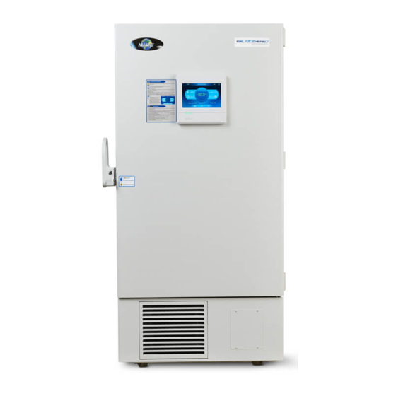
3.0 Parts of the Freezer Freezer Overview LCD Touchscreen Door Handle (With Lock) Component Access Panel Leveling Leg Caster OM0300 /2022 PRIL... -
Page 6: Inner Door Components
Inner Door Components Inner door handle: When replacing, remove the side screws of the handle. Outer door handle Balance valve Sealing strip of outer door: take out from the retaining groove when Integrated cabinet replacing. opening Sealing strip of inner door: take out from the Inner door: PU retaining groove when... - Page 7 Fixed cover for main internal temp. sensor. Test port 1 Mounting clip for stainless-steel shelf. Back threaded Zinc-coated inner hole liner. Test port 2 Trim strip of cabinet shelf. Engine compartment guard plate, right side Engine compartment guard plate, left side Power switch cover plate Inner door...
-
Page 8: Electrical Components
Threaded hole at back of cabinet Test port Power cord plug Inner door handle body, four-way structure loT module Electrical Components Main control Switching power Backup system panel board supply Remote alarm wiring Condenser fan 485 communication Lithium battery module port Power switch Thermocouple plate Battery switch... - Page 9 Main Control Panel Variable frequency Door 3-color 5V cold Printer Backup system Networking signal line switch lamp chain Networking Electro- magnetic lock Electro- magnetic lock Display panel Battery Balancing hole Condenser sensor Switching Condenser sensor power supply Ambient temp. sensor Master sensor Thermocouple...
- Page 10 Thermocouple Board exit of low stage evaporator entrance of low stage evaporator exit of low stage condenser exit of high stage condenser Main control panel entrance of high stage condenser Connect Main board Main sensor Backup system power supply line(option) OM0300 /2022 PRIL...
- Page 11 The antenna Tricolor board Screen control line The main control board and the HUB board connecting line Screen control line HUB board Main control board Speaker USB line,connect CN5 Fingerprint Line (optional) USB board Fingerprint module (Optional) Card reading board Connect CN2 OM0300 /2022...
-
Page 12: System Structure
System Structure Condenser Condensate Fan Condenser Sensor Oil Separator Low Pressure Switch Low Temperature Drying Filter High Temperature Drying Filter Blowing fan High temperature compressor Condensate fan Low temperature compressor Oil separator OM0300 /2022 PRIL... - Page 13 4 wide-voltage condensate fan Oil Separator High temperature Low temperature inverter 油分 inverter Low-temperature inverter The long line of frequency converter signal line connects to the low-temperature frequency converter, with the short-line connected to high-temperature frequency converter OM0300 /2022 PRIL...
-
Page 14: Process Overview
4.0 Process Overview Administrator Permission Entry method: press “login”, input password 8888888888 to enter the administrator interface. Connect the thermocouple sensor to the corresponding position on thermocouple board in electrical box, Suction line of high stage compressor: corresponding position is No.1 on thermocouple board, it states ①... - Page 15 [Setting Records] Input start time and end time, press “inquiry” to view setting records in this period time, press “download” to download setting record data. If press download without inputting time period, it will download setting record data for all time period. [Setting] Model: the model information for this unit, system self-determination Temperature calibration of tank: when real measured temperature of tank deviates from temperature...
- Page 16 Calibration if voltage: when displayed voltage value deviates from real measured voltage value, calibrate the display panel value, default value is 0, adjust range is -9V~9V, displayed value changes after calibration. Example: 215V is displayed on the machine, but the user measures that the voltage is 220V, in order to lessen the difference, the voltage deviation can be adjusted by +5℃.
- Page 17 [Input serial no.] To replace display panel, input the serial no. to produce bar code, in order to use a scanning gun and serial no. inquiry operation. Shielding function: if select one fault shielding and save, when this alarm occurs, it will not display on the screen.
- Page 18 [Update] Press “update” to update program with U disk [Alarm record] View and delete alarm record, can delete individual record, or delete all records [Factory reset] Factory reset: Clear all data and factory reset Alarm record clearance: wipe all alarm record, can’t recover Event record clearance: wipe all event record, can’t recover OM0300 /2022...
-
Page 19: Precautions
Precautions 1. After the first installation or moving of the equipment, rotate the horizontal support clockwise to support and fix 2. Room temperature should be kept below 28 ℃, as cooling efficiency rapidly decreases when the ambient the storage box on the ground, and then power on the freezer and use it 24h after its installation and fixing. temperature is higher than 32 ℃. -
Page 20: Technical Parameters
5.0 Technical Parameters Model NU-99729VFT Technical Parameters Orientation Vertical Climate type Control mode Microcomputer control LED display (minimum Display display accuracy 0.1℃) Temperature sensor PT100 Basic Parameters Volume (L) Voltage Frequency (V/ 100~230/50/60 Power (W) Current (Stable) (A) 7 (4.6) Internal dimensions 766*716*1310 (mm) (W*D*H) -
Page 21: Preventive Measures, Product Use And Daily Maintenance
6.0 Preventive Measures, Product Use and Daily Maintenance Principle of Ultra-Low Temperature Frequency Conversion Refrigeration The low-temperature refrigerator adopts a cascade refrigeration system which is usually composed of two or more refrigeration systems, referred to as high-temperature level and low-temperature level respectively. The high temperature level uses the medium-temperature refrigerant and the low-temperature level uses the low- temperature refrigerant, each of them is a complete refrigeration system;... -
Page 22: Working Principle Of Pressure Switch
Working Principle of Pressure Switch A. Principle: When the pressure in middle of the pipeline at the pressure switch exceeds 2.1MPa, the contact is disconnected and the low temperature cabinet stops, the pressure starts to drop; when the pressure drops to 1.35MPa, the contact is connected and the low-temperature cabinet is started;... - Page 23 d. After the low pressure is evacuated for an hour, the pressure gauge valve is closed, at which time the machine is required to remain in the negative pressure state for more than one hour to check whether the machine system is in a vacuum state, or observe if the pressure gauge has recovered during this period;...
- Page 24 The requirements for quantity accuracy (g) of the refrigerant filling of the ultra-low temperature cabinet • product system is very strict, so the branch must prepare a standard electronic scale with an error of 2g before maintenance. Fig. 6 Filling Amount of Refrigerant Refrigerant (type/ quantity) Refrigerant (type/ quantity) 2 Model...
-
Page 25: Refrigeration Schematic And Wiring Diagram
7.0 Refrigeration Schematic and Wiring Diagram Refrigeration Diagram NOTE: Variable drive controllers do are independent of each compressor and may not need to be changed out at the same time if one fails. OM0300 /2022 PRIL... -
Page 26: Wiring Diagram
Wiring Diagram OM0300 /2022 PRIL... -
Page 27: Control System
8.0 Control System Control of Compressor 1. Start-stop control a. Normal control i. Start-up condition: The temperature inside the box is more than and equal to the set temperature + P20 (default 5), which lasts for 30s (EEP). Stop condition: The temperature inside the box is less than and equal to the set temperature + NOTE: P20 and P21 range is adjustable, P20 default value is 5 (i.e. - Page 28 d. Control of the Compressor is Normal and the Low Temperature Starts for 1 min (EEP), then the low- temperature compressor start. i. 220V power supply When the power supply is less than and equal to 184V (EEP) which lasts for 10s (EEP), the high and low-temperature compressor keeps start-up and does not stop.
-
Page 29: Control Of Fans
PT100: Temperature inside the box Tset: setting temperature inside the box The range of K * (PT100 – Tset + 0 ℃ (P19)) is: -20 (P15) - 20 (P16) K * (PT100 – Tset + 0℃(P19)): -20(P15)~20(P16) F range is: 2000 (P17) - 4500 (P18) 3. - Page 30 ii. When the battery voltage is more than and equal to 13.5 V (EEP) but less than 14.3 (EEP) V, If the charging current is more than 270mA (EEP), the duty ratio is decreased by 1% (EEP). If the charging current is less than 250mA (EEP), the duty ratio is increased by 1% (EEP). c.
-
Page 31: Heating Wire Control
When the battery temperature is higher than and equal to 65 ℃ (EEP), the charge and discharge of the 5. Lithium Battery Charge / Discharge Temperature Protection When the battery temperature is lower than 55 ℃ (EEP), the charge and discharge of the battery are battery are stopped. -
Page 32: Installation And Disassembly Process
9.0 Installation and Disassembly Process Installation Location 1. Avoid direct sunlight 2. The surrounding air circulation is good 3. Avoid large quantities of dust 5. Ambient temperature: 5 ℃ to 28 ℃, max. 32 ℃, the most ideal temperature is 18 ℃ to 25 ℃, and air 4. -
Page 33: Moving The Unit
Fixed bolt Fixed bolt Fixed bolt A Moving the Unit 1. Difficulty in entering the door: If the door height of the room door that the customer requests to be placed cannot be accessed without bottom tray and there is no other way, the cover of the engine room may be removed and open the outer door by 180 degrees. -
Page 34: Removal Of Display Cover
NOTE: Be sure to install in place, otherwise it will cause safety and performance problems! Avoid damaging and scratching the storage box during handling. During handling, the maximum angle of inclination shall not exceed 45 ° (included angle with the horizontal direction) to avoid the failure of refrigeration system which could affect normal use. -
Page 35: Troubleshooting And Frequently Asked Questions
10.0 Troubleshooting and Frequently Asked Questions 10.1 Problems and Possible Solutions 1. The display temperature is inconsistent with the actual test temperature of the machine: Because the display temperature is the temperature of a certain point inside the box, the temperature detected by the user is the temperature of another point inside the box, and the inconsistent position must cause different temperature, and meanwhile, there is certain error between the test tools of the users and our temperature sensing probe. -
Page 36: Troubleshooting Table
10.2 Troubleshooting Table Problem Cause analysis Maintenance measures Use a multimeter to measure the resistance of the switch or Power switch or fuse failure fuse. if the switch is confirmed damaged, replace the fuse or power switch Check whether the connecting plug of the connecting wire of Connecting plug of the engine engine room is damaged or the wire harness is damaged and room connector is damaged. - Page 37 Check whether the patch cord of fan falls or is not plugged, Wiring of fan fails and reprocess the thread ends and realign for installation Check whether the fan blade produces the noise of touching Fan blade is blocked by foreign wall during rotating or does not rotate, handle the foreign body matters on and around the blade, and keep the blade running...
- Page 38 Check whether the battery has exceeded the service life Check whether the wiring terminal on the battery switch is in good Low battery alarm goes off connection or whether the switch is damaged. Low battery alarm when the battery capacity ≤ Check whether the charging circuit is normal: after the 10.5V refrigerator is powered strongly for 5min, test whether the...
-
Page 39: High Alarm Processing Method
10.3 High Alarm Processing Method Refrigerator display temperature ≥ high temperature alarm setting temperature (high temperature alarm No (Normal condition) setting temperature ≥ operation setting Check LED lamp of display panel and control circuit "Alarm" lamp flashes; "High Temp." alarm lamp flashes Check control board buzzer and After 15 minutes of light flashing alarm, the... -
Page 40: Low Alarm Processing Method
10.4 Low Alarm Processing Method Refrigerator display temperature ≤ low temperature alarm setting temperature (low temperature alarm No (Normal condition) setting temperature ≤ operation setting temperature -5 ℃) Check LED lamp of display panel and "Alarm" lamp flashes; "Low Temp." alarm lamp control circuit flashes After 15 minutes of light flashing alarm, the... -
Page 41: Diagram And Spare Parts List
11.0 Diagram and Spare Parts List Qty Per Nu-99729VFT Spare Part Name Unit Unit HAI - 270806173 Cabinet Assembly HAI - 0270103284A Fixer for Door Lock HAI - 0270100327G Outer Door Handle HAI - 0270101174B Lock Fixer for Outer Door HAI - 0270103284B Handle... - Page 42 HAI - 0270103236A Aluminum Shelter HAI - 270102159 Air Filter HAI - 0074090520C Chart Recorder HAI - 0070101872C Duplex All-Round Caster Bottom Frame Assemblage, HAI - 270103737 Dot Welding HAI - 270806167 Electric Chamber Assembly Left Side Guard Plate HAI - 0270103138B Assemblage HAI -...
Need help?
Do you have a question about the BLIZZARD NU-99729VFT and is the answer not in the manual?
Questions and answers