Table of Contents
Advertisement
Quick Links
Advertisement
Table of Contents

Related Manuals for Sunfar V220 Series


Summary of Contents for Sunfar V220 Series
- Page 2 Thanks for choosing V220 Series Low Power closed-Loop Vector Inverter produced by Shenzhen Sunfar Electric Technologies Co, Ltd. This Manual is the operating manual for V220 Series Low Power Closed-Loop Vector Inverter. It provides all relevant instructions and precautions for installation, wiring, functional parameters, daily care and maintenance, fault diagnosis and troubleshooting of V220 series inverter.
-
Page 3: Table Of Contents
CATALOG 1. PRODUCT CONFIRMATION AND OPERATION CAUTIONS................1.1 PRODUCT CONFIRMATION......................... 1.1.1 CONFIRMATION OF FREQUENCY INVERTER BODY AND ACCESSORIES....1.1.2 NAMEPLATE OF FREQUENCY INVERTER................1.2 SAFETY CAUTIONS............................1.2.1 NOTICES DURING INSTALLATION..................... 1.2.2 SAFETY CAUTION FOR WIRING....................1.2.3 SAFETY CAUTION FOR RUNNING OPERATION..............1.2.4 SAFETY CAUTION FOR MAINTENANCE CHECK.............. - Page 4 3.2.3 EXTENSION OF EXTERNAL CONNECTION................3.3 DISASSEMBLY OF TERMINAL COVER..................... 3.4 INSTALLATION SIZE OF PANEL........................3.5 DISASSEMBLY AND INSTALLATION OF EXPANSION BOARD............3.6 INSTALLATION AND DISASSEMBLY OF FUNCTION BOARD.............. 3.7 INSTALLATION SIZE OF FREQUENCY INVERTER................4. WIRING OF FREQUENCY INVERTER........................4.1 CAUTIONS OF WIRING..........................
- Page 5 6.2.7 CARRIER FREQUENCY......................... 6.2.8 V/F PARAMETERS AND OVERLOAD PROTECTION.............. 6.2.9 STEADY RUNNING......................... 6.2.10 PARAMETERS OF MOTOR 1...................... 6.2.11 PARAMETER MEASUREMENT AND PRE-EXCITATION............6.2.12 MULTIFUNCTIONAL INPUT TERMINAL................... 6.2.13 MULTIFUNCTIONAL OUTPUT TERMINAL................6.2.14 PULSE INPUT..........................6.2.15 PULSE OUTPUT..........................6.2.16 ANALOG INPUT..........................6.2.17 ANALOG INPUT CURVE CORRECTION.................. 6.2.18 ANALOG OUTPUT.........................
- Page 6 6.2.41 VIRTUAL INPUT AND OUTPUT....................6.2.42 PROTECTION FUNCTION CONFIGURATION PARAMETER..........6.2.43 CORRECTION PARAMETER...................... 6.2.44 SPECIAL FUNCTIONAL PARAMETERS................... 6.2.45 OTHER CONFIGURATION PARAMETERS................6.2.46 HISTORICAL FAULT RECORDING.................... 6.2.47 OPERATION STATUS AT THE LAST FAULT................6.2.48 BASIC STATUS PARAMETER..................... 6.2.49 AUXILIARY STATUS PARAMETER.................... 6.2.50 MODBUS FIELDBUS STATUS PARAMETER................
- Page 7 7.20 HOPPING FREQUENCY (GROUP F5.0)....................7.21 BUILT-IN AUXILIARY TIMER (GROUP F5.1)................... 7.22 BUILT-IN AUXILIARY COUNTER (GROUP F5.2)..................7.23 AUXILIARY FUNCTIONS (GROUP F5.3)....................7.24 MULTI-STAGE FREQUENCY SETTING (GROUP F6.0)................ 7.25 SIMPLE PROGRAMMABLE MULTI-STEP RUNNING (GROUP F6.1)..........7.26 SWING FREQUENCY OPERATION (GROUP F6.2)................7.27 PROCESS PID (4MS CONTROL CYCLE) (GROUP F7.0)..............
- Page 8 10 DESCRIPTION OF COMMUNICATION PROTOCOL.................... 10.1 PROTOCOL OVERVIEW..........................10.2 INTERFACE AND TRANSMISSION METHOD..................10.3 DATA STRUCTURE............................10.4 PARAMETER CONFIGURATION FOR FREQUENCY INVERTERS........... 10.5 BRIEF INTRODUCTION OF FUNCTIONS....................10.6 ACCESS ADDRESS SUMMARY........................ 10.7 DETAILED MODBUS ADDRESS-FINDING DISTRIBUTION……………………………………. 1) COIL ADDRESS SUMMARY………………………………………………………………… 2) DISCRETE INPUT ADDRESS SUMMARY…………………………………………………….
-
Page 9: Product Confirmation And Operation Cautions
Read this instruction carefully prior to installation, wiring, operation and maintenance, to ensure proper operation of this product. "Tips", "Attention", " Warning " and " Danger " in this operation manual are defined as follow. V220 Series Low Power Closed-Loop Vector Inverter User Manual... -
Page 10: Notices During Installation
6. Confirm that the motor and frequency converter are adaptive with each other, otherwise, the motor can be damaged or frequency converter protection can be caused. 7. Brake resistor can not be connected onto the (+), (-) of DC bus directly, otherwise, there can be fire risk. V220 Series Low Power Closed-Loop Vector Inverter User Manual... -
Page 11: Safety Caution For Running Operation
3. Operation of single-phase motors can not be achieved with this model frequency inverter. Even when input with single phase, there is three-phase output, please apply with three-phase motor. V220 Series Low Power Closed-Loop Vector Inverter User Manual... -
Page 12: Ambient Environment
2. If serious accident or serious losses caused due to the failure of this product, please install safety device for this product, otherwise, there can be accident. V220 Series Low Power Closed-Loop Vector Inverter User Manual... -
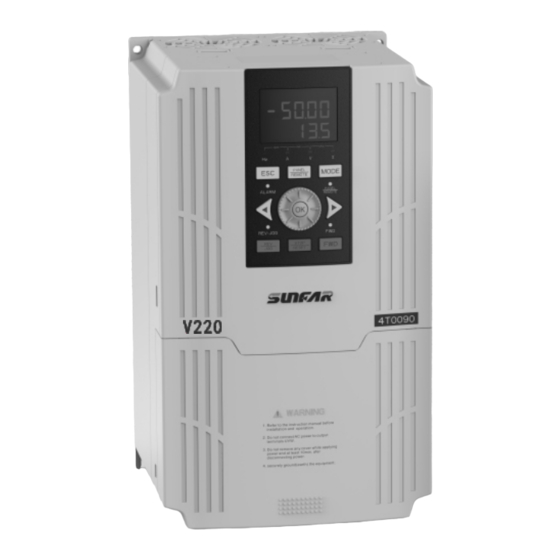
Page 13: Product Introduction 5
Wiring entrace of major loop 2.3 MODEL TABLE Rated capacity Adaptive motor Rated current Voltage Model (KVA) (KW) V220-2S0004 V220-2S0007 0.75 V220-2S0011 Single Phase V220-2S0015 220V V220-2S0022 10.0 V220-2S0030 14.0 V220-2S0040 16.5 V220 Series Low Power Closed-Loop Vector Inverter User Manual... -
Page 14: Product Technical Index And Specifications
Two-circuit 0~10V analog output signal (can be set to 0~20mA Analog output current output mode) Standard one group of AC 250V/2A normally open and closed Contact output contacts, 1~6 groups normally open and closed contacts extensible V220 Series Low Power Closed-Loop Vector Inverter User Manual... - Page 15 Start enabling, operation enabling, start General delay, over current suppression, over voltage/under voltage Functions suppression, V/F custom curve, analog input curve correction, line brake detection, textile machinery disturbance (frequency swing) operation V220 Series Low Power Closed-Loop Vector Inverter User Manual...
- Page 16 0~1000m. The output current capability drops by 10% for every rise Altitude of 1000 m Environment Ambient Working ambient temperature: -10°C ~ +45°C temperature Storage ambient temperature: -20°C ~ +60°C Humidity Blow 95%, no condensed water Vibration < 6m/s V220 Series Low Power Closed-Loop Vector Inverter User Manual...
-
Page 17: Installation Of Frequency Inverter
If necessary to install at the place with more than 1000m height above sea level, please de-rate operation. See 2.4 product technical indexes and specifications for details. V220 Series Low Power Closed-Loop Vector Inverter User Manual... -
Page 18: Size And Assembly Of Operation Panel
10 Installation of frequency inverter V220 Series Low Power Closed-Loop Vector Inverter User Manual...
Need help?
Do you have a question about the V220 Series and is the answer not in the manual?
Questions and answers