Table of Contents
Advertisement
Thanks for choosing the E500 series universal low-power inverter produced
by Shenzhen Sunfar Electric Technologies Co., Ltd.
This Manual is the operating manual for E500 series universal low-power
inverters. It provides all relevant instructions and precautions for installation,
wiring, functional parameters, daily care and maintenance, fault diagnosis and
troubleshooting of E500 series inverters.
In order to use this series of inverters correctly, guarantee product's best
performance and ensure safety of users and equipment, be sure to read this
manual carefully before using E500 series inverters. Improper use may cause
abnormity and malfunction of the inverter, reduce its service life and even
damage equipments and lead to personal injury and death etc.
This user manual is delivered with the device. Please keep it properly for
future overhaul and maintenance.
Owing to constant improvement of products, all data may be changed without
further notice.
User Manual of E500 Series Universal Low-Power Inverter
Version V1.0
Revision Date: Mar. 2015
HRW Limited
Preface
SHENZHEN SUNFAR ELECTRIC TECHNOLOGIES CO., Ltd.
admin@hrw.hk
www.hrw.hk
Advertisement
Table of Contents

Related Manuals for Sunfar E500-2S0004(B)


Summary of Contents for Sunfar E500-2S0004(B)
- Page 1 Preface Thanks for choosing the E500 series universal low-power inverter produced by Shenzhen Sunfar Electric Technologies Co., Ltd. This Manual is the operating manual for E500 series universal low-power inverters. It provides all relevant instructions and precautions for installation, wiring, functional parameters, daily care and maintenance, fault diagnosis and troubleshooting of E500 series inverters.
- Page 2 HRW Limited admin@hrw.hk www.hrw.hk...
-
Page 3: Table Of Contents
CONTENTS 1 PRODUCT INTRODUCTION ............1 1.1 D ..........1 ESCRIPTION OF INVERTER MODEL 1.2 M ............1 ODEL OF INVERTER SERIES 1.3 P ....1 RODUCT APPEARANCE AND NAME OF COMPONENTS 1.4 P ... 2 RODUCT TECHNICAL INDICATORS AND SPECIFICATIONS 2 INVERTER INSTALLATION ............ - Page 4 7.1 P ....66 ROTECTION FUNCTION AND COUNTERMEASURES 7.2 F ............. 67 AULT RECORD QUERY 7.3 F ................68 AULT RESET APPENDIX I: SUNFAR SELF-DEFINED COMMUNICATION PROTOCOL ..................69 1.1 O ................69 VERVIEW 1.2 B ....70 TRUCTURE AND ROTOCOL PECIFICATION 1.3 D...
- Page 5 Precautions I Precautions E500 series universal low-power inverters are applicable to general industrial single-phase and three-phase AC asynchronous motors. If this inverter is used for equipment which is failed and may cause personal injury (e.g. nuclear control system, aviation system, safety equipment and instruments), please take care and consult with the manufacturer;...
-
Page 6: Safety Precautions
II Precautions ◆ Weight and dimension Net weight Gross weight Outer box Model (KG) (KG) dimension(mm) E500-2S0004(B) 195×115×175 E500-2S0007(B) 195×115×175 E500-4T0007(B) 223×135×195 E500-4T0015(B)/E500-2S0015(B) 223×135×195 E500-4T0022(B)/E500-2S0022(B) 223×135×195 E500-4T0030(B)/E500-2S0030(B) 270×160×215 E500-4T0040(B)/E500-2S0040(B) 270×160×215 We have strict quality assurance system for the products in terms of manufacturing, packing and transportation. - Page 7 Precautions III 2.2 Wiring 1. Wire diameter shall be selected according to applicable electric code, and wiring shall be done by qualified technicians. 2. Wiring shall not be started unless the power supply of the inverter is completely disconnected. 3. The grounding terminal of the inverter must be reliably grounded; otherwise, there can be a danger of electric shock.
- Page 8 IV Precautions 3. With long-term operation at low speed, the operation life of motor can be affected due to the poorer heat dissipation effect. In this case, special frequency converter shall be selected or the motor’s load shall be decreased. 4.
-
Page 9: Description Of Inverter Model
Product Introduction 1 1 Product Introduction 1.1 Description of inverter model E500 - 4 T 0007 (B) Product series number Derived Product model Universal With braking unit and 485 E500 low-power communication inverter Voltage grade Adaptive motor power 380V (KW) 220V 0004 0007... -
Page 10: Product Technical Indicators And Specifications
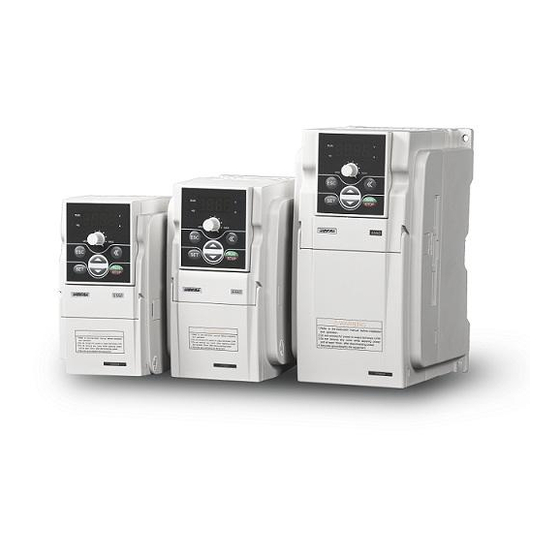
2 Product Introduction Operating panel 操作面板 Operating panel 操作面板 Housing 壳体 Housing 壳体 Control loop cable inlet 控制回路电缆入口 Control loop cable inlet 控制回路电缆入口 Main loop cable inlet 主回路电缆入口 Main loop cable inlet 主回路电缆入口 Bottom installation hole 底部安装孔 Bottom guide rail fastener Bottom installation hole 底部导轨扣... -
Page 11: Product Introduction 3
Optional built-in PID Internal integrated optimized PID controller, allowing controller for simple closed-loop control. RS485 communication SUNFAR user-defined protocol or MODBUS and linkage control protocol. Analog DC voltage 0-10V, and DC current 0-20mA (optional) input... - Page 12 4 Product Introduction Surrounding -10ºC to +40ºC (no freezing) temperature Surrounding 90% below (no frosting) humidity Surrounding Indoor (Free of direct sunlight, corrosion, flammable Environment environment gas, oil mist and dusts) Altitude Below 1000m Protecting grade IP20 Cooling mode Forced air cooling Installation mode Rail type /wall-mounted E500 Series Universal Low-Power Inverter...
-
Page 13: Inverter Installation
Inverter Installation 5 2 Inverter Installation 2.1 Environmental requirements This series of inverters are wall-mounted products and shall be vertically installed to facilitate air circulation and heat dissipation. Following attentions shall be paid for selecting installation environments. The ambient temperature shall be within -10℃-40 . ℃... - Page 14 6 Inverter Installation Fan exhaust 风扇排气 变 频 器 Baffle plate 导 流隔板 50mm 50mm 50mm以上 50mm以上 变 频 WARNING 1.Refer to the instruction manual before installation and operation. 2.Do not connect AC power to output terminals UVW. 器 3.Do not remove any cover while applying power and at least 10min.
-
Page 15: Inverter Installation 7
Inverter Installation 7 E500 2S0015 Figure 2-2-B Inverter Installation Dimension 2 Applicable models: E500-2S0015 (B) ~2S0040 (B)/E500-4T0007 (B) ~4T0040 (B), As shown in Figure 2-2-B The specific installation dimensions of E500 series inverters are shown in following table: Inverter model Inverter model Screw (three-phase... -
Page 16: Installation Dimension Of Inverters
8 Inverter Installation 2.2.2 Installation dimensions of optional 41.1 60.7 28.8 17.6 Figure 2-2-C Small Keyboard Installation Dimension 3 6 .7 1 7 .6 2 0 .7 Figure 2-2-D Installation Dimension of Small Keyboard Base Note: Assemble with M3 screws and pay attention to the whole site and opening dimension within the dotted lines. - Page 17 Inverter Installation 9 69.5 Figure 2-2-F Opening Dimension of Small Keyboard Base Note: See Figure 2-2-F for the recommended opening dimension of small keyboard base E500 Series Universal Low-Power Inverter HRW Limited admin@hrw.hk www.hrw.hk...
- Page 18 HRW Limited admin@hrw.hk www.hrw.hk...
-
Page 19: Inverter Wiring
Inverter Wiring 9 3 Inverter Wiring 3.1 Wiring precautions Make sure intermediate circuit breaker is connected between the frequency inverter and power supply to avoid expanded accident when the frequency inverter is faulty. In order to reduce electromagnetic interference, please connect surge sorber on the coil of electromagnetic contactor, relay and etc. -
Page 20: Wiring Of Peripheral Elements
10 Function Parameter Table Motor 电 动 机 变 频 器 Inverter RC absorber 阻 容 吸 收 装 置 Figure 3-1 Forbidding connecting a RC absorber at the output terminal 3.2 Wiring of peripheral elements Braking resistor 制动电阻 AC Power AC 电源... - Page 21 Inverter Wiring 11 Contactor It can conveniently control power-supply and power disconnection of the inverter, and the power-on and power-off of the motor. AC reactor 1) To promote power factor; 2) To reduce harmonic input of the inverter against the grid; 3) Weaken influenced caused by unbalanced voltage of three-phase power supply.
-
Page 22: Basic Wiring
12 Function Parameter Table 3.3 Basic wiring Three-phase circuit breaker 三相断路器 Motor 电动机 × Three-phase 三相电源 × power supply × 接大地 To earth Failure alarm output 故障报警输出 Programmable 可编程输入端子 input terminal To braking resistor 外接制动电阻 Auxiliary DC power supply 辅助直流电源 Voltmeter (0-10V) 电压表(0~10V)... -
Page 23: Wiring Of Main Loop Terminal
Inverter Wiring 13 3.4 Wiring of main loop terminal Category I main loop terminal Applicable models : E500-2S0004(B)~E500-2S0007(B) Symbol Function DC side voltage positive terminal Braking resistor can be connected between PP and PB To grid single-phase AC 220V L1, L2 Earthing 大地... -
Page 24: Wiring Of Control Loop Terminal
14 Function Parameter Table 3.5 Wiring of control loop terminal (1) Diagram of control loop terminal → Voltage/current input jumper terminal TA TC X1 X2 X3 X4 OC CM 24V VS AO GND RS+ RS- (2) Function description of control loop terminal Terminal Type Terminal function... -
Page 25: Operating Panel
STOP 下 降 Down Figure 4-1 Operating Panel Sketch Note: E500 series keyboard port can be compatible with SUNFAR E300 and E310 series, and other series keyboard is not compatible. Do not make confusion. 4.1 Function description of keys Keys... -
Page 26: Panel Operating Method
16 Function Parameter Table Keys Function Description RUN/STOP command key. When the command channel selects control panel ([F0.02] =###0), this key is effective. The key is a trigger key. When the inverter is at the stop STOP status, press this key to input stop command to stop running. At the inverter fault status, this key is also used as the fault reset key. -
Page 27: List Of Status Monitoring Parameters
Operating Panel 17 (2) Parameter inquiry and modification (example) 4.3 List of status monitoring parameters Monitoring Content Unit code d-00 Inverter’s current output frequency d-01 Inverter’s current output current (effective value) d-02 Inverter’s current output voltage (effective value) d-03 Motor revolution d-04 Voltage at the DC terminal in the inverter d-05... -
Page 28: Simple Operation Of The Inverter
18 Function Parameter Table Monitoring Content Unit code d-10 Input terminal status d-11 Module temperature ºC d-12 Analog output AO d-13 Timer value d-14 Reserve d-15 Reserve d-16 Reserve d-17 Reserve d-18 Reserve d-19 Reserve d-20 Reserve d-21 Reserve d-22 Reserve d-23 First fault record... - Page 29 Operating Panel 19 4.4.2 Simple running It is absolutely forbidden to connect the power cord to the output U, V, W of the frequency inverter. Three-phase circuit breaker 三相断路器 Motor 电动机 × Three-phase × 三相电源 power supply × Earthing 接大地 Figure 4-2 Simple Running Wiring Diagram ①...
-
Page 30: Function Parameter Table
20 Function Parameter Table 5 Function Parameter Table Parameter Function Setting Range and Minimum Default Modifica- Name Type Code Description unit setting tion limit 0: Digital setting 1: External analog quantity 2: External communication Frequency F0.00 input channel 3: Panel potentiometer 4: Selection of external terminal... - Page 31 Function Parameter Table Parameter Function Setting Range and Minimum Default Modifica- Name Type Code Description unit setting tion limit 0: Straight line Acceleration and acceleration and deceleration deceleration F0.07 characteristic 1: S Curve parameter acceleration and deceleration F0.08 Carrier frequency 1.5 ~ 10.0kHz 0: Asynchronous F0.09 Modulation mode...
- Page 32 22 Function Parameter Table Parameter Function Setting Range and Minimum Default Modifica- Name Type Code Description unit setting tion limit F0.20 Reserve Parameter F0.21 protection 0~9999 password F0.22 UP/DW speed 0.1~50.0Hz F0.23 PWM period 1.0~10.0ms F0.24 Reserve AI input lower F1.00 0.0 V ~ [F1.01] F1.00...
- Page 33 Function Parameter Table Parameter Function Setting Range and Minimum Default Modifica- Name Type Code Description unit setting tion limit LED Units: OC output selection 0: OC output positive characteristics 1: OC output negative characteristics OC and relay output LED Tens: relay F1.15 0000 characteristic...
- Page 34 24 Function Parameter Table Parameter Function Setting Range and Minimum Default Modifica- Name Type Code Description unit setting tion limit 0: External voltage + panel potentiometer 1: External voltage+ panel potentiometer + Digital setting 2:Communication + external voltage 3: Communication + external voltage + panel potentiometer 4:Communication +...
- Page 35 Function Parameter Table Parameter Function Setting Range and Minimum Default Modifica- Name Type Code Description unit setting tion limit F2.10 Reserve F2.11 V/F frequency 1 0.0~[F2.13] F2.12 V/F voltage 1 0~[F2.14] F2.13 V/F frequency 2 [F2.11]~[F2.15] F2.14 V/F voltage 2 [F2.12]~[F2.16] F2.15 V/F frequency 3 [F2.13]~[F0.12]...
- Page 36 26 Function Parameter Table Parameter Function Setting Range and Minimum Default Modifica- Name Type Code Description unit setting tion limit Under voltage 180 ~ 230V / 200/ F3.11 protection level 360 ~ 460V Overvoltage 350 ~ 400V / 360/ F3.12 suppression level 700 ~ 800V Current...
- Page 37 0: No check Communication 1:Even parity check F4.00 0114 × setting 2: Odd parity check LED Hundreds: protocol selection 0: SUNFAR self-defined protocol 1: MODBUS communication protocol LED Kilobit: Reserve F4.01 Local address 0 ~ 30 E500 Series Universal Low-Power Inverter HRW Limited admin@hrw.hk...
- Page 38 28 Function Parameter Table Parameter Function Setting Range and Minimum Default Modifica- Name Type Code Description unit setting tion limit Local response F4.02 0 ~ 1000ms delay LED Units: Inverter main/slave setting 0: This inverter is a slave machine 1: This inverter is a main machine LED Tens: Selection of action after...
- Page 39 Function Parameter Table Parameter Function Setting Range and Minimum Default Modifica- Name Type Code Description unit setting tion limit PID adjustment F5.09 0.0~100.0% 100.0 frequency range Breakage F5.10 0.0~50.0% detection value Breakage F5.11 detection delay 0.1~10.0 Sec time F5.12 Reserve F5.22 Cutting function F6.00...
-
Page 40: Function Details
30 Function Parameter Table 6 Function details 6.1 Basic running parameter group F0.00 Selection of frequency input channel/mode Setting range: 0 ~ 5 It is used to select setting channel/mode of inverter’s running frequency. 0: Digital setting The inverter’s set frequency is set by parameter [F0.01]. 1: External analog quantity The running frequency is set by external input voltage signal (0~10V) or current signal (0~20mA);... - Page 41 Functional Details 31 F0.01 Frequency digital setting Setting range: 0.0 Hz ~upper limiting frequency When frequency input channel selects digital setting ([F0.00] = 0), inverter’s output frequency is determined by this value. When the operating panel is at the normal monitoring status, simply press key to modify this parameter.
- Page 42 32 Function Parameter Table LED Tens: selection of running command mode 0: Two-line mode1 (default mode) command Stop command FEW command REV command Terminal status Two-line mode requires selecting one input terminal X1~X4 as forward control temrinal FWD and the other input terminal X1~X4 as reverse control terminal REV (refer to parameter [F1.08]~[F1.11]).
- Page 43 Functional Details 33 3: Special mode for terminal machine: This function is only applicable to special occasions such as terminal machine. X1 is used as the approach switch counting and stop signal, and X2 is start signal. LED Hundreds: REV prevention 0: REV prevention void 1: REV prevention effective LED Kilobit: Power-on auto start...
- Page 44 34 Function Parameter Table F0.07 Acceleration and deceleration characteristics parameter Setting range: 0~1 It is used to set the acceleration and deceleration characteristic parameter of inverters (fratile binary system setting). LED UNITS: setting of inverter’s acceleration and deceleration curve type. (...
- Page 45 Functional Details 35 the motor load is too high, or the inverter is failed due to above reasons, it is suggested to appropriately decrease the carrier frequency to improve thermal characteristics of the inverter. F0.09 Modulation mode Setting range: 0 ~ 1 This function is for selection of modulation mode.
- Page 46 36 Function Parameter Table Voltage 电 压 [F0.13] [F0.11] Boost 提 升 voltage 电 压 [F0.12] 频 率 Frequency Figure 6-4 Torque Boost Sketch F0.12 Basic running frequency Setting range: 5. 0Hz ~ upper limiting frequency F0.13 Maximum output voltage Setting range: 25 ~ 250V/50 ~ 500V The basic running frequency is the minimum frequency at the maximum voltage of inverter output.
- Page 47 Functional Details 37 F0.18 Setting of auxiliary functions Setting range: 0000 ~ 0011 LED UNITS: Running direction 0: Consistent with the set direction 1: Reverse with the set direction LED Tens: Jog priority selection 0: Jog priority highest 1. Jog priority lowest If the jog priority is set to the highest, the pripirty of each freqeuncy source is as below: Priority level...
-
Page 48: Analog Input Output Parameter Group
38 Function Parameter Table F0.20 Reserve F0.21 Parameter password protection Setting range: 0000 ~ 9999 F0.22 UP/DW speed Setting range: 0.1~50.0Hz When [F0.00]=5, [F1.28]=9 or 10, and input terminal selects UP or DW function, frequency can be set through external terminals. This parameter is used to set the increasing and decreasing speed of the frequency set by external terminal. - Page 49 Functional Details 39 F1.03 Minimum set frequency Setting range: 0.0Hz ~ [F1.04] F1.04 Maximum set frequency Setting range: [F1.03] ~ [F0.04] The corresponding relationship between the analog input quantity and set frequency is shown in Figure 6-6. Frequency Output frequency F[1.04] F[1.03] Voltage...
- Page 50 40 Function Parameter Table F1.06 AO output lower limit Setting range: 0.0 V ~ [F1.07] F1.07 AO output upper limit Setting range: [F1.06] ~ 10.0 V Define the maximum value and minimum value of analog output AO output signal. Refer to figure 6-7. [F1.06] Upper limiting Output...
- Page 51 Functional Details 41 4: FWD jog control 5: REV jog control When the external terminal of running command channel selection is effective, this parameter can define the input terminal of external jog signals. 6: Frequency set channel selection 1 7: Frequency set channel selection 2 When the frequency input channel is set to be external terminal selection (F0.00=4), the frequency set channel of the inverter will be determined by the status of these two terminals, and for its corresponding relationship, please refer...
- Page 52 42 Function Parameter Table 16: External fault input When the terminal set by this parameter is engaged, it indicates that the external equipment is faulty. At this time, in order to ensure safety of the equipment, the inverter will lock the input and displays the external fault signal Fu.16. 17: Disconnection input When the terminal set by this parameter is engaged, it indicates disconnection fault of external equipments.
- Page 53 Functional Details 43 26: Reserve 27: Reserve 28: Splitting machine infrared signal 29: Splitting machine approaching switch signal F1.12 Selection of input channel characteristics Setting range: 0000~ 1111H It is used to select characteristics of external digital input: LED UNITS: Define characteristics of X1 input channel 0: positive characteristics 1: negative characteristics LED Tens: Define characteristics of X 2 input channels...
- Page 54 44 Function Parameter Table Figure 6-8 internal circuit of OC output terminal For connecting external inductive elements (e.g. relay coil), freewheel diode D must to be connected in parallel. 0: Inverter is running When the inverter is running, it outputs effective signals, and when the inverter is at stop, it outputs void signals.
- Page 55 Functional Details 45 signals. Output terminal High Higgh resister resistor Ferquency Output frequency FDT level [F1.18] [F1.19] [F1.19] Figure 6-10 Frequency Level Detection Signal (FDT) 3: Overload detection When the inverter’s output current exceeds the overload alarm level, after the set alarm delay time, it outputs effective signals.
- Page 56 46 Function Parameter Table terminal outputs effective signals; otherwise, it outputs void signals. 6: Running at zero speed When the inverter’s running command is effective and the output frequency is at 0, this terminal outputs effective signals; otherwise, it outputs void signals. 7: Under voltage stop When the inverter’s DC side voltage is lower than the specified value, the inverter stops running, and this terminal outputs effective signals;...
- Page 57 Functional Details 47 F1. 15 OC and relay output characteristics Setting range: 0000 ~ 0011 Select polarity of OC output and relay output according to digits. When it is set to “1”, the output polarity is reverse. F1. 16 Relay action delay Setting range: 0.0 ~ 5.0 Sec This parameter is used to set the delay time for change of status of relay output signals...
- Page 58 48 Function Parameter Table F1.22 Reserve F1.23 Reserve F1.24 Batter number of terminal machine Setting range: 1~100 F1.25 Specified count value Setting range: 1~[F1.26] F1.26 Final count value Setting range: [F1.25]~60000 Count related to F1.24, F1.25, F1.26, which only can use external termincal X3. Please refer to parameter [F1.10] setting as 22.
-
Page 59: Auxiliary Running Parameter Group
Functional Details 49 6.3 Auxiliary running parameter group F2.00 Start frequency Setting range: 0.0 ~ 50.0Hz F2.01 Start frequency duration Setting range: 0.0 ~ 20.0Sec This functional parameter group is used to define characteristics relevant with start mode. See Figure 6-12. For the system with large inertia, heavy load and high requirements of start torque, the start frequency can effectively overcome the problem of difficulty start. - Page 60 50 Function Parameter Table F2.03 DC braking initial frequency at stop Setting range: 0.0 ~ [F0.04] F2.04 DC current at stop Setting range: 0.0 ~ 100% F2.05 DC braking time at stop Setting range: 0 ~20.0 Sec. This parameter group is used to set DC braking parameters at stop. During the process of DC braking initial frequency ([F2.03]) at stop setting inverter stop, when the output frequency is lower than the set parameter, the inverter will lock output and enable DC braking function.
- Page 61 Functional Details 51 Figure 6-13 Sketch of acceleration torque and braking torque % F2.07 Motor overload protecting coefficient Setting range: 50 ~ 110 ( This parameter is used to set inverter’s sensitivity of thermal relay protection for load motor. When the rated current of the load motor is not matching with the inverter’s rated current, it is applicable to set this value to provide correct thermal protection over the motor.
- Page 62 52 Function Parameter Table 直流侧 DC side voltage 电压 [F2.08] [F2.08] [F2.08]-50V [F2.08]-50V Braking unit action 制动单元动作 时间 Time Figure 6-14 Dynamic Braking F2.09 ~ F2.10 Reserve F2.11 V/F frequency 1 Setting range: 0.0~[F2.13] F2.12 V/F voltage 1 Setting range: 0.0~[F2.14] F2.13 V/F frequency 2 Setting range: [F2.11]~[F2.15]...
-
Page 63: Multi-Speed And Senior Running Parameter Group
Functional Details 53 F2.17 Reserve F2.18 Automatic voltage regulation Setting range: 0~2 The automatic voltage regulation function is for protecting inverter’s voltage from fluctuating with input voltage fluctuation. When the grid voltage varies greatly and it desired that the motor has comparatively stable stator voltage and current, this function should be enabled. - Page 64 54 Function Parameter Table Running liner speed (d-8) = F3.07 X Output frequency (d-0) Set liner speed (d-9) = F3.07 X Set frequency (d-6) F3.08 Monitoring parameter selection Setting range: 0 ~ 22 This parameter is used to determine the display contents on the operating panel at the monitoring status.
- Page 65 Functional Details 55 operation of the inverter. Note : when the grid voltage is too low, the motor’s output torque will reduce. For occasions with constant power load and constant torque load, excessive low grid voltage will cause incease of inverter input current, hence leading to reduction of inverter operation reliablity.
- Page 66 56 Function Parameter Table F3.15 ~F3.16 Reserve F3.17 Multi-speed running mode Setting range: 0000~0042H Setting of basic characteristics of multi-speed running(fratile decimal system setting) LED UNITS: Simple PLC action selection 0: Simple PLC void 1: Simple PLC effective 2: Simple PLC conditionally effective When LED Units is selected to 1 (PLC effective), after the inverter has started, at the frequency channel priority allowed status, the inverter will enter the simple PLC running status.
- Page 67 Functional Details 57 2: Mode of keeping final value The basic running way is the same as the mode 0. After the completion of the single cycle, the inverter will not stop after completion of a single cycle and continues running at the last speed for which the time is not set to zero. Other process is the same as model 1.
- Page 68 58 Function Parameter Table F3.22 PLC multi-stage running direction Setting range: 0000 ~1111H Define PLC multi-speed running direction (fratile binary system setting) LED UNITS: Stage 1 direction selection 0: FEW 1: REV LED Tens: Stage 2 direction selection 0: FEW 1: REV LED Hundreds: Stage 3 direction selection 0: FEW...
- Page 69 Functional Details 59 F3.26 Swing frequency running setting Setting range: 0000~0012H This parameter is used to set basic characteristics of swing frequency running (fratile decimal system setting) LED Units: Swing frequency function enabling selection 0: Swing frequency function disabled 1: Swing frequency function effective 2: Swing frequency function conditionally effective When the external swing frequency input terminal is effective (the swing frequency input terminal is selected by functional parameter [F1.08]~[F1.11]),...
-
Page 70: Communication Functional Parameter Group
60 Function Parameter Table frequency, i.e. the decceleration time during runing cycle at swing frequency. When the triangular wave ascending time is the running time from the swing frequency lower limit to swing frequency upper limit during running at the swing frequency, i.e. - Page 71 With the SUNFAR self-defined protocol, the address 31 is the broadcasting address, and 0 represents the broadcasting address in the case of MODBUS communication. For broadcasting data, the slave machine executes command but does not give feedback of corresponding data (see the appendix of communication protocol).
-
Page 72: Pid Parameter Group
62 Function Parameter Table LED Tens: Action selection after communication failure 0: Shutdown 1: Maintaining current status LED Hundreds: Data return selection 0: Normal return of data 1: Do not return data LED Kilobit: Reserve F4.04 Communication overtime detection time Setting range: 0.1 ~ 10.0 Sec When this inverter has not received correct data signal beyond the interval defined by this parameter, it is judged that the inverter has subject to communication failure. - Page 73 Functional Details 63 Ti S ? ? ? Controlled ? ? ? ? Td*S+1 Target value system ? ? ? Feedback value Figure 6-18 PID Function Sketch F5.00 PID function selection Setting range: 0 ~ 1 0: PID function disabled 1: PID function enabled F5.01 PID setting channel...
-
Page 74: Special Machine Parameter Group
64 Function Parameter Table F5.06 Ratio grain Setting range: 0.0~10.0 F5.07 Integral time Setting range: 0.01~10.00Sec F5.08 Derivative time Setting range: 0.00~10.00Sec It is parameter group of inner PID controlled. F5.09 PID adjustment frequency range Setting range: 0 ~ 100% This parameter is used to set the upper limit frequency to be a adjusted by PID, which is the percentage of maximum output frequency corresponding to the maximum PID value. - Page 75 Functional Details 65 F6.03 Start delay Setting range:: 0.01~10.00 F6.04 Stop delay Setting range: 0.01~10.00 This group of parameters defines the cutting start delay and stop delay, which is related to the length of the first plate and last plate. F6.05 Reserve F6.06 Liner cutting running mode...
-
Page 76: Fault Diagnosis And Countermeasures
66 Fault Diagnosis And Countermeasures 7 Fault Diagnosis And Countermeasures 7.1 Protection function and countermeasures Fault Code Fault Description Possible Reasons Solutions 1. The acceleration time is too short. 1. Extend acceleration time. Over current 2. Start the rotating motor 2. -
Page 77: Fault Record Query
Fault Diagnosis And Countermeasures 67 Fault Code Fault Description Possible Reasons Solutions 1. The load is too large. 1. Reduce load. 2. The acceleration time is 2. Extend the acceleration too short. time. 3. The protection factor Fu.13 Motor overload 3. -
Page 78: Fault Reset
68 Fault Diagnosis And Countermeasures Monitoring Monitoring content content project project The output current of the last d-23 The first fault record d-28 fault recently The output voltage of the d-24 The second fault record d-29 last fault recently The direct voltage of the last d-25 The third fault record d-30... -
Page 79: Appendix I: Sunfar Self-Defined Communication
1.1.2 Application Scope 1. Applicable products The series of SUNFAR inverters, e.g. C300 series, C320 series, the E500 series, E280 series, etc. can be compatible with the communication protocols of the other brands of inverters. -
Page 80: Bus Structure And Protocol Specification
1.2.2 Protocol Specification E500 series is applicable to MODBUS (please refer to Appendix II for details) and SUNFAR custom communication protocol, which is to be described as follows: SUNFAR custom communication protocol is a serial master-slave communication protocol, only one device (main machine) in the network can set... - Page 81 (named as response); as for broadcast message sent by main machine, it’s not necessary for slave machine to make any feed- back to main machine. 1. Communication setting F4.00=X0XX, select SUNFAR custom communication protocol. 2. Data structure Available in three types of data transmission formats: (1) 1-bit start bit, 8-bit data bit, 1-bit stop bit, no check.
- Page 82 72 SUNFAR Self-Defined Communication Protocol (3) If the inverter fails to receive any message after detecting time from communication timeout (function code: F4.04), it’s identified as off-line fault, and then the inverter determines operating status of slave machine in line with setting content set by communication aid function (function code: F4.03).
- Page 83 SUNFAR Self-Defined Communication Protocol 73 1. Command frame of main machine 10 11 12 13 14 15 16 Station Command Address area Data area Check area address area 2. Response frame of slave machine General description of data definition in data frame...
- Page 84 74 SUNFAR Self-Defined Communication Protocol (3) Command classification Command classification exists in the data frame sent by main machine, which is used to define tasks of the frame data to be completed. Frame size varies based on different command classification. Command classification is defined as below:...
- Page 85 SUNFAR Self-Defined Communication Protocol 75 (5) Slave machine response The response of slave machine to data sent by main machine is mainly used to feedback implementation of slave machine to command frame of main machine, which exists in all types of data frame. The slave machine response is defined as...
- Page 86 76 SUNFAR Self-Defined Communication Protocol (6) Status feedback The basic running status of slave machine responded from slave machine to main machine exists in all types of data frame (Slave machine responds the 4 and 5 bit). Data Operation Data...
-
Page 87: Description Of Frame Format
SUNFAR Self-Defined Communication Protocol 77 1.3 Description of frame format When frame header, frame end and checksum in data frame sent by main machine are abnormal, slave machine possibly fails to make normal response. 1.3.1 Command classification 0- Read status and feature information of... - Page 88 78 SUNFAR Self-Defined Communication Protocol Data classification Feature information (Slave machine response ) (Sent by main machine) Read program version of slave Reserve Reserve machine Main Read operation Main machine information of machine Reserve Reserve Reserve Reserve frequency slave machine...
- Page 89 SUNFAR Self-Defined Communication Protocol 79 Data subentry: is corresponding to number of monitoring parameter items of the inverter; as for E500 series inverter, the number of monitoring parameter items is shown as below: Monitoring Data subentry Slave machine response data...
- Page 90 80 SUNFAR Self-Defined Communication Protocol 1.3.4 Command classification 3- Modify function code parameters in inverter RAM area. 1.3.5 Command classification 5- Modify function code parameters in inverter EPROM area Main machine sending frame size is 18 bytes, while slave machine response frame size is 18 types.
- Page 91 SUNFAR Self-Defined Communication Protocol 81 1.3.6 Command classification 4- Send control command Main machine sending frame size is 15 bytes, while slave machine response frame size is 18 types. In normal operation of inverter, the type of frame data is applicable to maximum extent.
-
Page 92: Example
82 SUNFAR Self-Defined Communication Protocol 1.4 Example 1.4.1 Read status and feature information of slave machine (Command classification 0) Data setting: Read model of slave machine Sent by Frame Slave Command Operation Data Data Frame main Checksum header address type... - Page 93 SUNFAR Self-Defined Communication Protocol 83 Data feedback: Return to set frequency of 50.0Hz. Slave Frame Slave Slave Status Display Data Operating Frame machine Checksum header address response feedback parameter subentry Data response Number of bits 30 32 30 31 30 30...
- Page 94 84 SUNFAR Self-Defined Communication Protocol 1.4.4 Modify function code parameters in inverter RAM area (Command classification 3) Data setting: modify digital set frequency [F0.01] = 50.0Hz, stop without storage. Sent by Frame Slave Command Operating Data Data setting Frame main...
- Page 95 SUNFAR Self-Defined Communication Protocol 85 Data feedback: No. 0 inverter receives data in normal condition. Slave Frame Slave Slave Status Monitoring Operating Frame machine Checksum header address response feedback item data response Number of bits 30 30 30 32 30 30...
-
Page 96: Appendix Ii: Modbus Protocol Specification
86 MODBUS Protocol Appendix II: MODBUS Protocol Specification 1. Communication setting F4.00=X1XX, select MODBUS RTU protocol; Note: X represents that the bit is arbitrary number. 2. Communication function Complete communication between upper machine and inverter, including sending operation command to inverter, setting running frequency, rewriting function code parameter, reading running status of inverter, monitoring parameter, fault message and function code parameter. - Page 97 MODBUS Protocol 87 Slave machine response: Number of reading bytes PDU PART Reading content (2*Number of registers) Data length (Byte) 2*Number of registers (2) Function code 06: Rewrite operation command, running frequency and functional parameter of single inverter. Sent by main machine: Register initial address Register data PDU PART...
- Page 98 88 MODBUS Protocol Objection code indicates error category: Objection code Corresponding error Illegal function code Illegal data address Overhanging data Invalid operation of slave machine Too much read-write parameters Reserve read-write, implicit parameter Slave machine running forbids modifying data Data modification is protected by password Failure in read-write parameter CRC CHECK: CRC CHECK...
- Page 99 MODBUS Protocol 89 3. Definition of communication parameter address Distribution of inverter parameter address: Register implication Register address space High is the number of function code group, while low is mark Functional parameter number of function code, e.g. F1.11, the register address is F10B. High is 0xD0 and low is monitoring mark number, e.g.
-
Page 100: Example
90 MODBUS Protocol Inverter status code Indication 0x0011 In FWD acceleration 0x0012 In REV acceleration 0x0013 Instant stop and restart 0x0014 FWD deceleration 0x0015 REV deceleration 0x0016 Slave machine stays in DC braking condition 0x0020 Slave machine stays in fault condition (4)The high fault message code is 0, while low is corresponding to the rear mark number of inverter fault code-Fu., e.g. - Page 101 MODBUS Protocol 91 (3). Read current running frequency, output current, inverter response frequency 50.0Hz and output current 1.1A of inverter. Main machine request: Slave Register initial address Number of registers CRC CHECK Function machine code High High High address Slave machine response: Slave 1st register data 2nd register data...
-
Page 102: Appendix Iii: Brake Resistor Selection
The following content refers to introducing brake resistor power and resistance value recommended to be employed for SUNFAR inverter. Based on loading condition, user can modify value properly in line with the range specified by SUNFAR inverter. Brake Applicable... - Page 103 MODBUS Protocol 93 The above configuration is to realize 100% braking torque, it’s necessary to select value in actual use based on braking condition. In case of weak braking, please reduce brake resistance properly and increase brake resistance power class in proportion. The brake resistance power is the estimated value in working condition of brake resistance interval;...
Need help?
Do you have a question about the E500-2S0004(B) and is the answer not in the manual?
Questions and answers