
Related Manuals for CEM 9915


Summary of Contents for CEM 9915
- Page 1 OPERATING INSTRUCTION AUTORANGING DIGITAL MULTIMETE MODEL 9915 AUTO Ω μ ¡ ã ¡ ã...
-
Page 2: Safety Information
SAFETY INFORMATION The following safety information must be observed to insure maximum personal safety during the operation at this meter: Do not use the meter if the meter or test leads look damaged, or if you suspect that the meter is not operating properly. Never ground yourself when taking electrical measurements. -
Page 3: Safety Symbols
Never apply voltage or current to the meter that exceeds the specified maximum: SAFETY SYMBOLS This symbol adjacent to another symbol, terminal or operating device indicates that the operator must refer to an explanation in the Operating Instructions to avoid personal injury or damage to the meter. WARNING This WARNING symbol indicates a potentially hazardous situation, which if not avoided, could... -
Page 4: Controls And Jacks
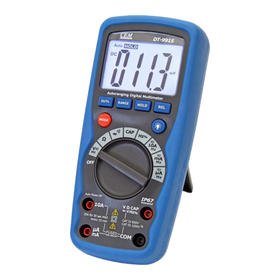
hazardous voltages. For maximum safety, the meter and its test leads should not be handled when these terminals are energized. CONTROLS AND JACKS AUTO Ω μ ¡ ã ¡ ã Large 4000 count Liquid Crystal Display with symbolic signs. Range pushbutton. -
Page 5: Symbols And Annunciators
Frequency/ %Duty button. Mode pushbutton. Data Hold pushbutton Relative pushbutton. Backlight pushbutton. Function switch 10A (positive) input jack for uA/mA input jack Positive input jack DC/AC Voltage, %duty cycle, Ohms, Diode, Continuity, Capacitance, measurements COM (negative) input jack. SYMBOLS AND ANNUNCIATORS Continuity Low Battery Diode... -
Page 6: Specifications
SPECIFICATIONS The instrument complies with: EN61010-1. Insulation: Class2, Double insulation. Overvoltage category: CATIII 1000V, CATIV600V. Display: 4000 counts LCD display with function indication. Polarity: Automatic, (-) negative polarity indication. Overrange: “OL” mark indication. Low battery indication: The “BAT” is displayed when the battery voltage drops below the operating level. - Page 7 Weight: Approx.: 375g. Accuracy is given at 18 o C to 28 o C (65 o F to 83 o F), less than 70 % RH DC Voltage (Auto-ranging) Range Resolution Accuracy 400.0mV 0.1mV +0.5% of rdg + 2 dgts 4.000V +1.2% of rdg + 2 dgts 40.00V...
- Page 8 DC Current (Auto-ranging for uA and mA) Range Resolution Accuracy 400.0uA 0.1uA +1.0% of rdg + 3 dgts 4000uA +1.5% of rdg + 3 dgts 40.00mA 10uA 400.0mA 100uA 10mA +2.5% of rdg + 5 dgts Overload Protection: 0.5A / 1000V and 10A / 1000V Fuse. Maximum Input: 400mA dc or 400mA ac rms on uA / mA ranges, 10A dc or ac rms on 10A range.
- Page 9 Resistance (Auto-ranging) Range Resolution Accuracy +1.2% of rdg + 4 dgts 400.0Ω 0.1Ω +1.0% of rdg + 2 dgts 4.000kΩ 1Ω +1.2% of rdg + 2 dgts 40.00kΩ 10Ω 400.0kΩ 100Ω 4.000MΩ 1kΩ +2.0% of rdg + 3 dgts 40.00MΩ 10kΩ...
- Page 10 Sensitivity: <0.5V RMS while ≤1MHz ; Sensitivity: >3V RMS while >1MHz ; Overload protection: 600V dc or ac rms. Duty Cycle Range Resolution Accuracy 0.1%~99.9% 0.1% +1.2% of rdg + 2 dgts Pulse width: >100us, <100ms; Frequency width: 5Hz – 150kHz Sensitivity: <0.5V RMS Overload protection: 600V dc or ac rms.
-
Page 11: Operation
OPERATION WARNING: Risk of electrocution. High-voltage circuits, both AC and DC, are very dangerous and should be measured with great care. ALWAYS turn the function switch to the OFF position when the meter is not in use. This meter has Auto OFF that automatically shuts the meter OFF if 15 minutes elapse between uses. -
Page 12: Data Hold Button
situations requiring that a range be manually selected, perform the following: Press the RANGE button. The “AUTO” display indicator will turn off. Press the RANGE button to step through the available ranges until you select the range you want. 3. Press and hold the RANGE button for 2 seconds to exit the ManualRanging mode and return to AutoRanging. -
Page 13: Backlight Button
1. Perform any measurement as described in the operating instructions. 2. Press the RELATIVE button to store the reading in the display and the "REL" indicator will appear on the display. 3. The display will now indicate the difference between the stored value and the measured value. -
Page 14: Dc Voltage Measurements
Note: The above data only for reference. DC VOLTAGE MEASUREMENTS CAUTION: Do not measure DC voltages if a motor on the circuit is being switched ON or OFF. Large voltage surges may occur that can damage the meter. 1. Set the function switch to the V DC position (“mV” will appear in the display). -
Page 15: Dc Current Measurements
CAUTION: Do not measure AC voltages if a motor on the circuit is being switched ON or OFF. Large voltage surges may occur that can damage the meter. 1. Set the function switch to the V AC position. 2. Insert the black test lead banana plug into the negative (COM) jack and the red test lead banana plug into the positive (V) jack. -
Page 16: Ac Current Measurements
4. For current measurements up to 10A DC, set the function switch to the A position and insert the red test lead banana plug into the 10A jack. 5. Press the AC/DC button until “DC” appears in the display. 6. Remove power from the circuit under test, then open up the circuit at the point where you wish to measure current. - Page 17 the mA range and insert the red test lead banana plug into the (mA) jack. 4. For current measurements up to 10A AC, set the function switch to the A position and insert the red test lead banana plug into the 10A jack. 5.
-
Page 18: Resistance Measurements
RESISTANCE MEASUREMENTS WARNING: To avoid electric shock, disconnect power to the unit under test and discharge all capacitors before taking any resistance measurements. Remove the batteries and unplug the line cords. 1. Set the function switch to the Ω position. 2. -
Page 19: Diode Test
will sound. The display will also show the actual resistance. DIODE TEST WARNING: To avoid electric shock, do not test any diode that has voltage on it. 1. Set the function switch to position. 2. Press the button until the symbol appears in the display. -
Page 20: Frequency Measurement
FREQUENCY MEASUREMENT 1. Set the function switch to the FREQ position. 2. Insert the black test lead banana plug into the negative (-) jack (COM) and the red test lead banana plug into the positive (+) jack (F). 3. Touch the test probe tips to the circuit under test. 4. -
Page 21: Replacing The Battery
REPLACING THE BATTERY WARNING: To avoid electric shock, disconnect the test leads from any source of voltage before removing the battery door. When the batteries become exhausted or drop below the operating voltage, “BAT” will appear in the right-hand side of the LCD display. The battery should be replaced. -
Page 22: Replacing The Fuses
WARNING: To avoid electric shock, do not operate the meter until the battery door is in place and fastened securely. NOTE: If your meter does not work properly, check the fuses and battery to make sure that they are still good and that they are properly inserted. REPLACING THE FUSES WARNING: To avoid electric shock, disconnect the test leads from any source of voltage before removing the fuse door.
Need help?
Do you have a question about the 9915 and is the answer not in the manual?
Questions and answers