Table of Contents
Advertisement
Quick Links
Advertisement
Table of Contents

Related Manuals for ThermoSphere TSMEB-5

Summary of Contents for ThermoSphere TSMEB-5
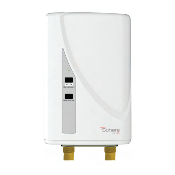
- Page 1 INSTALL GUIDE HEATING | WATER MICRO ELECTRIC BOILER Live well...
- Page 2 ThermoSphere CONNECT and fill in the form. Nice and easy! After you sign up instantly start uploading your receipts to gain your rewards! We can‘t wait for you to join the ThermoSphere CONNECT community and start getting the rewards you deserve for every registered installation!
-
Page 3: Table Of Contents
Flow rates Installation procedure Mounting to the wall Electrical terminals and connections Wiring diagrams for single and tandem installations Plumbing connections Preparing the unit for use Operating instructions Diagnostics Manual intervention Product registration Mounting hole template 0800 019 5899 hello@thermosphere.com... -
Page 4: Warranty Terms And Conditions
Warranty terms & conditions for ThermoSphere Micro Electric Boilers For the ThermoSphere Micro Electric Boiler (TSMEB), Thermogroup Ltd will repair or, if necessary, at its sole discretion, replace the TSMEB, which falls within the Warranty Periods and Territory specified below, subject to the warranty conditions and the warranty exclusions. Warranty Period within the United Kingdom is 3 years from the date of purchase by the consumer as defined by the Competition and Consumer Act 2010. -
Page 5: Installation Checklist
ThermoSphere nor its Distributors will be liable for any damages due to failure to comply with the installation and operating instructions outlined in this manual or through improper use. -
Page 6: Component Guide
Component guide This is a guide to all of the components and parts that make up a ThermoSphere Micro Electric Boiler. It will familiarise you with the component parts of the unit and will assist you during the installation process. Full details for wall mounting, electrical and plumbing installation are provided in the following sections. -
Page 7: Introduction To Single And Tandem Systems
Supply Power Supply Total Supply Supply Model @ +25°C Model @ +25°C (kW) cable (kW) cable increase increase TSMEB-5 TSMEB-5 4.8 ea 20 (x2) (x2) TSMEB-6 TSMEB-6 6.0 ea 25 (x2) (x2) TSMEB-7 TSMEB-7 7.2 ea 30 (x2) (x2) TSMEB-8 TSMEB-8 8.4 ea... -
Page 8: Installation Options
Installation options The suggested installation options show how ThermoSphere Micro Electric Boilers, either single or tandem units, can be fitted in bathrooms, kitchens, to heat pump systems and as a hot water supply to appliances or underfloor heating. Please note that the location and installation of the unit is not limited to the options shown here. -
Page 9: Specifications
IP44. Appliance must be installed inside only. Ambient temperatures 5°C +. Drain unit if the ambient temperature is likely to drop below 5°C Standards Warranty 3 years Electrical specifications Model TSMEB-5 TSMEB-6 TSMEB-7 TSMEB-8 TSMEB-10 Install type Single Tandem Single... -
Page 10: Flow Rates
Flow rates Flow rates Temperature increase TSMEB-5 TSMEB-6 TSMEB-7 TSMEB-8 TSMEB-10 required (°C) Install type Single Tandem Single Tandem Single Tandem Single Tandem Single Tandem 15°C 11.4 13.8 25°C Max flow rate (Litres per minute) based on temperature increase 35°C 45°C... -
Page 11: Installation Procedure
If the LED is slowly blinking GREEN, the unit is in standby mode and is ready for use. Turning hot water on will initiate the heating process and hot water should exit from the point of use water outlet. When the TSMEB is operating the LED will illuminate as fast blinking GREEN. 0800 019 5899 hello@thermosphere.com... -
Page 12: Mounting To The Wall
When mounting the unit onto a rough surface (ie: a brick wall or similar), a backing board should be mounted to the wall. The unit can then be mounted onto the backing board. This will allow the cover to be properly fitted to the unit. Mounting screw holes Mains supply cable gland fitting 0800 019 5899 hello@thermosphere.com... -
Page 13: Electrical Terminals And Connections
Electrical terminals and connections Electric supply cable gland Printed circuit board assembly (PCBA) Terminal block Display PCB PCBA reset button Display PCB plug and cable 0800 019 5899 hello@thermosphere.com... -
Page 14: Wiring Diagrams For Single And Tandem Installations
Wiring diagrams for single unit installations Single unit wiring 230VAC 230VAC Supply Supply All ThermoSphere Micro Electric Boilers must be fitted with their own correctly sized RCBO and an isolation switch in-line with the fixed wiring to the electrical 30mA 30mA supply. -
Page 15: Plumbing Connections
Important information and warnings! ThermoSphere nor its Distributors will be liable for any damages caused by failure to comply with the installation and operating instructions outlined in this manual – specifically in this instance where the specified water pressure limiting valve and shutoff valve type, as indicated, must be installed with this unit. -
Page 16: Preparing The Unit For Use
This process must be followed after installation and prior to first use ThermoSphere Micro Electric Boilers must be primed after installation and before the first use. Priming is also required after the electricity supply to the unit has been turned off or removed, for example after a power failure or isolation of the electrical supply. -
Page 17: Operating Instructions
This cannot be resolved by switching the unit off temperature. and on again. Manual intervention is required. If this occurs you should call ThermoSphere to tell us the error code and we will arrange for a service technician to help resolve the problem either remotely or via a site visit if required. -
Page 18: Diagnostics
Other than the inlet filter, there are no user serviceable parts inside a ThermoSphere Micro Electric Boiler. In case of an irresolvable or error or mechanical lockout please call ThermoSphere and tell us the error code. We will arrange for a support technician to try to resolve the issue remotely or via a site visit. -
Page 19: Manual Intervention
LED remains either flashing or illuminated and error condition is still present. There are NO If the user serviceable parts, other than the inlet filter, inside the housing so no further action can be taken. Call for a qualified service electrician to attend site and attempt repair. 0800 019 5899 hello@thermosphere.com... -
Page 20: Product Registration
Please fill in both the installer details and product details tables below to ensure that the home or property owner has all the information they need to register the product and also get technical help from ThermoSphere should the need arise. Important information and warnings! The installer must complete the information on this page and hand a copy to the home owner to keep for their records. - Page 21 Notes 0800 019 5899 hello@thermosphere.com...
- Page 22 Notes 0800 019 5899 hello@thermosphere.com...
-
Page 23: Mounting Hole Template
135mm Installation hole marking template 170mm... - Page 24 Thermogroup Ltd Bridge House Pattenden Lane Marden TN12 9QJ 0800 019 5899 hello@thermosphere.com www.thermosphere.com E&OE © Thermogroup Ltd 2022 Live well...
Need help?
Do you have a question about the TSMEB-5 and is the answer not in the manual?
Questions and answers