Table of Contents
Advertisement
Quick Links
Advertisement
Table of Contents

Related Manuals for SolarV EPEVER MT91

Summary of Contents for SolarV EPEVER MT91
- Page 1 USER MANUAL Remote Meter MT91...
-
Page 2: Table Of Contents
Contents 1. Safety Instructions ................... 1 2. Overview ....................2 3. Appearance ..................... 3 4. Installation Instructions ................6 5. Button Instruction ..................7 6. Real-time Interface .................. 8 7. Setting Interface ..................9 8. Error Codes ................... 17 9. Specifications ..................18 10. -
Page 3: Safety Instructions
Please avoid water, and other liquids enter into the product. There are no user-serviceable parts inside the product. Do not disassemble or attempt to repair it. Copyright © 2022 SolarV GmbH All rights reserved... -
Page 4: Overview
LCD screen, real-time dynamic display of system data Visually error codes, timely notification of warnings and faults Load ON/OFF button to control the load output directly Simple installation and friendly operation interface Copyright © 2022 SolarV GmbH All rights reserved... -
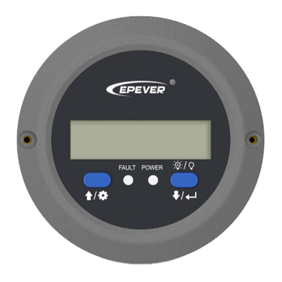
Page 5: Appearance
Load switch Fault indicator(red) Working indicator(blue) In the real-time interface, long press for 2 seconds to turn off the load (default on); long-press it again for 2 seconds to turn on the load. Copyright © 2022 SolarV GmbH All rights reserved... - Page 6 Buzzer Remote terminal Inve rter terminal ⚫ Definition of the inverter terminal/remote terminal: B +5V B +5V Copyright © 2022 SolarV GmbH All rights reserved...
-
Page 7: Installation Instructions
Surface mounting installation is recommended. Step 1: Locate based on the installation size (91mm) and drill two screw holes (no smaller than 77x52mm). Step 2: Use two PWM3*10 screws to fix the remote meter. Copyright © 2022 SolarV GmbH All rights reserved... - Page 8 Copyright © 2022 SolarV GmbH All rights reserved...
-
Page 9: Button Instruction
In the setting interface, click them to Click exit the parameter configuration interface. Press for In the real-time interface, press them for 2s to clear the faults. Long beep for parameter confirming and short beep for other operations. Copyright © 2022 SolarV GmbH All rights reserved... -
Page 10: Real-Time Interface
Battery voltage Load voltage Load current Load frequency Load power Note: means the load being ON status, means the load being OFF status. Copyright © 2022 SolarV GmbH All rights reserved... -
Page 11: Setting Interface
Step6: Click to exit the current interface. Power Saving Mode Users can enable the power saving mode and set the PSI/PSO value by the button (The minimum power step is 1VA). Copyright © 2022 SolarV GmbH All rights reserved... - Page 12 PSE parameter (OFF default) flashes. Step4: Click the button to set the PSE status. Select ON to enable the power saving mode. Select OFF to disable the power saving mode. Copyright © 2022 SolarV GmbH All rights reserved...
- Page 13 (Note: The setting parameter cannot exceeds the user define, or it will back to the initial value to start the loop). Copyright © 2022 SolarV GmbH All rights reserved...
- Page 14 (Note: The setting parameter cannot exceeds the user define, or it will back to the initial value to start the loop). Copyright © 2022 SolarV GmbH All rights reserved...
- Page 15 LCD backlight 30s/ 60s/100s(ON solid) time Power Saving ON/OFF Enable 20VA ~ (20%*rated Power Saving In 20VA power) Power Saving (20VA + PSI) ~ 40VA (50%*rated power) Baud Rate 115200 9600/115200 Select Copyright © 2022 SolarV GmbH All rights reserved...
- Page 16 24V: 29V 0.1V ② voltage 48V: 58V 48V: 43V-63.4V; step size 0.1V Over voltage 12V: 16V 12V: 12.5V~16.2V; step disconnect 24V: 32V size 0.1V ② voltage 48V: 64V 24V: 23V-32.2V; step size Copyright © 2022 SolarV GmbH All rights reserved...
- Page 17 ≥ Over voltage reconnect voltage +1V. B. Over voltage reconnect voltage ≥ Low voltage reconnect voltage. C. Low voltage reconnect voltage ≥ Low voltage disconnect voltage +1V. D. Low voltage disconnect voltage ≥ Low voltage limiting voltage(10.5/21/42V). Copyright © 2022 SolarV GmbH All rights reserved...
- Page 18 20V for the 12V system, not higher than 40V for the 24V system, and not higher than 80V for the 48V system; otherwise, the inverter may be damaged. Copyright © 2022 SolarV GmbH All rights reserved...
-
Page 19: Error Codes
(1Hz) Slowly Input low 5 beeps flashing voltage (1/4Hz) Fast Output short 5 beeps flashing circuit (1Hz) Slowly Output 5 beeps ON solid flashing overload (1/4Hz) Output voltage 5 beeps abnormal Copyright © 2022 SolarV GmbH All rights reserved... -
Page 20: Specifications
φ100mm X 50mm(Diameter X Height) Mounting size Φ3.5mm Mounting hole size Net Weight ① IPower-Plus supports MT91 whole functions, while IPower/NPower supports part MT91 functions; for detail supported functions, refer to user manual. Copyright © 2022 SolarV GmbH All rights reserved... -
Page 21: Dimension
10. Dimension Copyright © 2022 SolarV GmbH All rights reserved... - Page 22 Copyright © 2022 SolarV GmbH All rights reserved...
Need help?
Do you have a question about the EPEVER MT91 and is the answer not in the manual?
Questions and answers