Furuno FAR-2107 Series Installation Manual
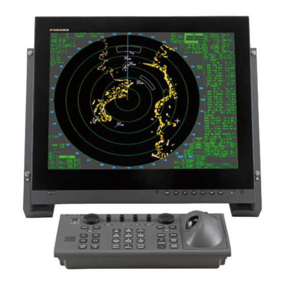
Standard radar console
Hide thumbs
Also See for FAR-2107 Series:
- Service manual (690 pages) ,
- Operator's manual (327 pages) ,
- Operator's manual (325 pages)

Related Manuals for Furuno FAR-2107 Series


Summary of Contents for Furuno FAR-2107 Series
- Page 1 Standard Console Installation Manual スタンダードコンソール 組込み要領書 STANDARD RADAR CONSOLE RCN-003/004 Model FAR-2107/2807シリーズレーダーコンソール FAR-2107/2807 Series Radar Console www.furuno.com...
- Page 2 Pub.No. C32-00406-E (2009, AKMU) RCN-003/004 00015088214...
-
Page 3: Installation Procedure
FAR-2807/2107 SERIES RADAR Console RCN-003/004 Installation Procedure The components of the radar console are either assembled at the factory or require assembly in the field. The purpose of this technical information is to provide the procedures for in-the-field installation of the processor unit, monitor unit, control unit and optional equipment of the radar console. There are eight types of radar console kits, as shown below. - Page 4 Mounting and wiring of the console Fasten the console. 1) Install a channel base (height: 100 mm), consulting with the shipyard. 2) Pass a lifting belt through the four eye bolts, hoist unit with crane and place unit on top of the channel base.
- Page 5 1) Set cushioning material on the console table and then place the monitor unit on the material, LCD side down. Connect the power cable (attached to the console), ground wire (attached to the console) and cable assembly (DVI-D/D S-LINK 5M, attached to the console) to the monitor unit. Power Cable Cable Clamp For MU-231CR...
- Page 6 Fasten the control unit to the console. 1) Remove the bottom cover of the console panel and the duct cover attached to the right side of the con- sole. 2) Set flush mount plate B (for RCU-014) or flush mount plate C (for RCU-015) to the console panel. 3) Set the control unit (RCU-014 or RCU-015) to the hole of the flush mount plate B or flush mount plate C, which is set to the console panel.
- Page 7 Fasten the Memory Card Interface Unit CU-200 (option) to the console (see the accessories at page A-12). 1) From the bottom cover of the console panel, remove round cap and replace it with grommet (supplied). 2) Set the CU-200 to the mounting bracket (19-023-3091) and fasten it with four washerhead screws (M4×10).
- Page 8 If the Video LAN converter IF-7100 is installed, do steps 6 to 7. Fasten the AC-DC Power Supply unit PR-240 (option) to the console with the optional VLC installation kit OP03-233. NOTE: If the DC power line is connected to IF-7100, the PR-240 is not required. 1) Fasten the PR-240 to the PR fixing plate (03-163-7276-0) with four upset hex.
- Page 9 5) Remove the cover of the terminal block of PR-240 then connect Terminal block on PR-240 (Top view) the AC power cable, the ground wire and the DC power cable to DC power cable DC power cable the terminal block. Ground wire Ground wire AC power cable...
- Page 10 4) Fasten the VLC fixing plate support (R/L) to VLC fixing plate support VLC fixing plate support the console with four upset UI bolts (M6×12). (2 pcs. left and right) (2 pcs. left and right) (4 pcs, left and right) (4 pcs, left and right) 5) Fasten the VLC fixing plate on the VLC fixing Stopper...
- Page 11 Remove the cover of the processor unit and open the upper case. Remove the transparent cover from the TB board (03P9342) by loosening four washer-head screws (M4×10). Disconnect all cable assemblies from the TB board and BRC board. These assemblies may be discarded. Processor Unit TB PCB 03P9342 J608...
- Page 12 12 Fasten the optional DVI-RGB conversion kit (OP03-180-4, see page A-11) in the processor unit. For further details, see chapter 4 in the installation manual of the FAR-2807/2107 se- ries. NOTE: If IF-7100 is installed, the optional DVI-RGB conversion kit is not installed in the console. DVI-RGB Conversion Board M3x8 (SLB-FRN4-A)
- Page 13 17 Connect power cable and ground wire (attached to the console) to the processor unit. Con- nect the signal cable assembly from the processor unit as shown below, routing it through the right duct. Fasten the duct cover to the duct. Connected Power Cable and Ground Wire Processor Unit Processor Unit...
- Page 14 19 Fasten the TB board and BRC board to the PCB mounting plate (see the figure below). Use the mounting fixture (03-163-7232, supplied as installation materials) to fasten the BRC board to TB board as shown below. 20 Connect the cable assembly (connected to the processor unit at step 11) to each port on the TB board and the BRC board.
- Page 15 24 Pass the antenna cable, power cable from switchboard and cables of external equipment through the cable entrance at the bottom of the console and connect them to appropriate ter- minal board at the bottom of the console. Connect the power cable (single phase) from ship’s switchboard for the main unit to TB1 on the terminal board.
- Page 16 Power Supply Unit (M5x12 SUS, 4 pcs.) (M4, 4 pcs.) PSU-007 MARINE RADAR TYPE SER.NO. COMPASS SAFE DISTANCE STEER FURUNO ELECTRIC CO., LTD. 9-52 Ashihara-Cho, 0560 Nishinomiya City, Japan MADE IN JAPAN TB-1 View Ground Wire Cable Assembly (TB1---J604) Clamp cable (AF214AMP-L550) °...
- Page 17 30 Connect the cable between the BNC connector converter and the DVI-RGB conversion kit as shown below. DSUB Connector Cable Cable Tie from Processor Unit CV-200N Procedure a) Fasten connector to BNC connector converter. b) Clamp cable at two place (attend to size of figure).
- Page 18 How to fasten the monitor unit MU-190 or MU-231 to the console 1 Follow steps 2 to 3 on page 2 of operator’s manual for MU-190 or MU-231. For MU-190, go to step 2. For MU-231, go to step 3. <MU-190>...
- Page 19 FAR-2807/2107 シ リ ーズレーダース タ ンダー ド コ ン ソール RCN-003/004 組込み据付け要領書 レーダー コ ン ソ ールは、 現地で各ユニ ッ ト を組み込んで設置す る 場合 と 、 工場にて組み込んだ も のを現地で設置す る 場合があ り ます。 本書では、 主 と し て現地で レーダー コ ン ソ ール内に標準構 成の制御部、...
- Page 20 設置 ・ 取付け ・ 結線 コ ン ソ ールを設置 し ます (詳細は外寸図参照)。 1) チ ャ ン ネルベース (高 さ 100mm) を造船所に製作 し て も ら い、 装備場所に設置 し ます。 2) ア イ ボル ト 4 ヵ 所にベル ト をかけて ク レーン で吊 り 上げ、 チ ャ ン ネルベースに載せます。 3) コ...
- Page 21 1) 操作卓の上に ク ッ シ ョ ン材を置いて、 その上に表示部 (LCD 部を下向き) を置き、 表示部に電源 ケーブル ( コ ン ソ ールに付属)、 アース線 ( コ ン ソ ールに付属)、 ケーブル組品 DVI-D/D S-LINK 5M ( コ ン ソ ールに付属) を取 り 付けます。 2) パネル フ ッ ク (表示部の付属品) を表示部取付穴付近にあ る穴 2 ヵ 所 (対角線の位置) にひ っ かけま す...
- Page 22 操作部を コ ン ソ ールに取 り 付けます。 1) 操作台 フ タ お よび コ ン ソ ール右側面内部のダ ク ト カバーを外 し ます。 2) フ ラ ッ シ ュ マウ ン ト B (RCU-014 用) または C (RCU-015 用) を操作台にはめ込みます。 3) 操作台にはめ込んだ フ ラ ッ シ ュ マウ ン ト B または C の角穴に、 操作部 (RCU-014 または 015) をは め込みます。...
- Page 23 メ モ リ ー カ ー ド イ ン タ ー フ ェ イ ス CU-200 (オプ シ ョ ン) を コ ン ソ ールに取 り 付けます (A-12 ページの付属品表参照)。 1) 操作台 フ タ に取 り 付け ら れている丸いキ ャ ッ プ を取 り 外 し て、 グ ロ メ ッ ト に取 り 替え ます。 2) CU-200 を...
- Page 24 ビデオ LAN コ ンバー タ IF-7100 を装備する場合は、 手順 6 ~手順 7 を行います。 VLC 現 地組込キ ッ ト OP03-233 (オプ シ ョ ン) を使っ て、 AC-DC 電源 PR-240 (オプ シ ョ ン) を コ ン ソ ールに取 り 付けます。 注) IF-7100 に直接 DC 電源を接続する場合は、 PR-240 を装備する必要はあ り ません。 1) 4 本の...
- Page 25 5) PR-240 の端子台のカバーを取 り 外 し 、 AC 電源ケーブル、 アース 線、 DC 電源ケーブルを端子台に接続 し ます。 PR-240 端子台 ケーブル 経由ダ ク ト 接続先 AC 電源ケーブル AC-IN ポー ト 左奥ダ ク ト に (FV2W-VVS2.0X2C-L1450) 通す アース線 アース端子 左奥ダ ク ト に (AF214AMM-L1700) 通す...
- Page 26 4) コ ン ソ ール筐体内部の左右に、 4 本の + ア プ セ ッ ト UI セムス A ボル ト (M6×12) を使 っ て、 VLC 固定板支え R/L を取 り 付けます。 5) VLC 固定板支え R/L の上に、 2 本の + ア プ セ ッ ト UI セム ス...
- Page 27 制御部のカバーを外 し 、 上ケース部を開けます。 4 本の±ナベセムスネジ ( M4×10) をゆるめて、 透明の基板カバーを外 し 、 TB 基板 03P9342 と BRC 基板 03P9485 に接続 さ れている ケーブル組品をすべて取 り 外 し ます。 外 し たケーブル組品は使用 し ません。 J608 J621 J612 J607 J620 J611 J606 J619 J605 J603 J604...
- Page 28 12 オプ シ ョ ンの DVI-RGB 変換キ ッ ト (OP03-180-4: A-11 ページ参照) は、 制御部内に取 り 付けます (詳細はレ ーダー本体に付属の装備要領書 4 章を参照 し て く だ さ い)。 注) IF-7100 を装備する場合は、 DVI-RGB 変換キ ッ ト を コ ン ソ ール内に装備する こ と はで き ません。...
- Page 29 コ ン ソ ールに付属の電源ケーブル、 アース線を制御部に接続 し 、 制御部か ら 出てい る信 号ケーブル組品を下図のよ う に配線 し ます。 信号ケーブル組品は コ ン ソ ール右側面のダ ク ト 内に通 し ます。 ダ ク ト カバーをはめ込みます。 レールに付いているバネ を指で押え て解除 し 、 制御部台を奥ま で挿入 し 、 +ア プ セ ッ ト セムスネジ...
- Page 30 19 TB 基板 と BRC 基板を コ ン ソ ール下部にあ る基板取付板の上に固定 し ます (下図参照)。 BRC 基板は、 工材の取付金具 (03-163-7232) を使 っ て、 下図のよ う に TB 基板に取 り 付 けます。 20 手順 11 で制御部に接続 し たケーブル組品を、 TB 基板 /BRC 基板のそれぞれのポー ト に接 続...
- Page 31 24 空中線部か ら のケーブル、 船内配電盤か らの電源ケーブル、 外部機器から のケーブルは、 コ ン ソ ール底面のケーブル導入口を通 し 、 コ ン ソ ール下部にあ る それぞれの端子台に接 続 し ます。 船内配電盤か ら の電源ケーブル と し て、 レーダー本体の電源 (単相) は TB1 へ、 FAR-2137S/ 2837S 用 の空中線部電源 (3φ) は TB2 へ接続 し ます。 FAR-2137S/2837S の空中線部への電源ケーブルは TB3 に 接続...
- Page 32 29 オプ シ ョ ンの BNC コ ネ ク タ コ ンバー タ は、 電源制御部の手前に ビ ス 2 本で取 り 付けます (下図参照)。 注) IF-7100 を装備する場合は、 BNC コ ネ ク タ コ ンバー タ を コ ン ソ ール内に装備する こ と は で...
- Page 33 30 BNC コ ネ ク タ コ ンバー タ と 制御部内の DVI-RGB 変換キ ッ ト 間のケーブルは下図のよ う に 配線 し ます。 コ ン ソ ールの前扉を取 り 付けます。 1) 下の扉受け (2 ヵ 所) に前扉を合わせてはめ込みます。 2) 前扉を コ ン ソ ールにサムス ク リ ュ ーネジ M6×25 (2 本) で固定 し ます。...
- Page 34 表示部 MU-190/MU-231 の取付け方法 MU-190 および MU-231 取扱説明書の 2 ページに記載 し ている、 手順 2 と 3 を行います。 MU-190 の場合は、 下記の手順 2 に進んで く だ さ い。 MU-231 の場合は、 下記の手順 3 に 進んで く だ さ い。 < MU-190 の場合> 1) M6 ナ ッ ト 、 バネ座金、 平座金を外 し て、 コ ン ソ ール前面か らパネル (20) を取 り 外 し ます。 2) 上記手順で外...
- Page 57 空中線部 操作部 パフォーマンスモニター ANTENNA UNIT CONTROL UNIT PERFORMANCE MONITOR PM-31 RSB-096/097 RCU-016 RW-4747 IV-3.5sq. 操作部 保護アース CONTROL UNIT RCU-014/015 NOT USED RS-232C TB BOARD 03P9342 制御部 PROCESSOR UNIT スタンダードコンソール RPU-013 STANDARD CONSOLE +12V RCN-003/004 DVI-RGB変換基板 +12V DVI-RGB CONVERSION BOARD SLB-FRN4-A GYRO CONVERTER RGBビデオコンバータ...
- Page 58 空中線型式 回転数 電源 空中線部 操作部 TB902 パフォーマンスモニター ANT. TYPE POWER SUPPLY ANTENNA UNIT CONTROL UNIT PERFORMANCE MONITOR RSB-098 200/220VAC RSB-098/099 PM-51 RCU-016 21/26 RSB-099 380/440VAC RSB-100/101/102 RSB-100 220VAC,50Hz RSB-101 220VAC,60Hz RSB-102 440VAC,60Hz RW-4747 IV-3.5sq. 保護アース 操作部 *1 *5 CONTROL UNIT RCU-014/015 J604 RS-232C...
- Page 59 空中線部 パフォーマンスモニター PERFORMANCE MONITOR ANTENNA UNIT PM-31 RSB-103 操作部 CONTROL UNIT RCU-016 RW-4747 IV-3.5sq. 保護アース *1 *5 送受信部 TRANSCEIVER UNIT 操作部 RTR-081A CONTROL UNIT RCU-014/015 GND *1 IV-8sq. RS-232C TB BOARD 03P9342 制御部 PROCESSOR UNIT スタンダードコンソール RPU-013 STANDARD CONSOLE RCN-003 +12V DVI-RGB変換基板...
- Page 60 空中線部 パフォーマンスモニター ANTENNA UNIT PERFORMANCE MONITOR 空中線型式 電源 PM-51 RSB-104/105 ANT. TYPE POWER SUPPLY 操作部 RSB-104 200/220VAC CONTROL UNIT RSB-105 380/440VAC RCU-016 LHPX-20D-ASSY, MPYCY-12,MAX.30m RW-4747 20/30m IV-3.5sq. 保護アース *1 *5 送受信部 TRANSCEIVER UNIT RTR-082 操作部 CONTROL UNIT RCU-014/015 *1 *5 IV-8sq.
Need help?
Do you have a question about the FAR-2107 Series and is the answer not in the manual?
Questions and answers