Table of Contents
Advertisement
Quick Links
Advertisement
Table of Contents

Related Manuals for Micro Rain MR40

Summary of Contents for Micro Rain MR40
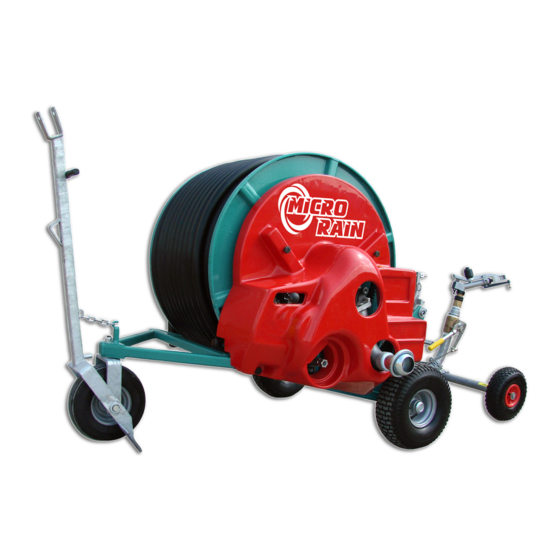
- Page 1 MICRO RAIN INSTRUCTION MANUAL OPERATION AND MAINTENANCE MR40, MR43...
- Page 2 Your safety is our first priority, and failure to follow these instructions may cause serious injury or death. Micro Rain is not responsible for machine failure if these procedures and operation instructions are not followed.
-
Page 3: Table Of Contents
TABLE OF CONTENTS Signs and their meaning.............3 - 4 Identification data..............5 Machine Controls..............6 Weight and Dimensions............7 Transport and Assembly.............8 - 9 Start-Up Maintenance Procedures.........10 - 12 Standard Hose Rewind............13 Quick Hose Rewind/Maintenance/Winterization....14 Care and Repair of P.E. Tube.........15 - 16 Troubleshooting..............17 Warnings.............. -
Page 4: Signs And Their Meaning
SIGNS PRESENT ON THE MACHINE AND THEIR MEANING 1. This sign indicates the operations and parts that may be risky for the safety of the operator. When seeing this sign read carefully the message which follows, and beware of possible risk of accident. 2. - Page 5 5. Before operating the machine, read the instruction manual carefully. 6. Before servicing or making any adjustments stop the machine and disconnect the supply line. 7. Do not stand between the hose reel and gun cart while machine is in operation.
-
Page 6: Identification Data
VALVE CAUTION GEARBOX WARNING CONDITIONS FOR MACHINE OPERATION The Micro Rain machine is designed to be used with clean water suitable for irrigation. This machine is not designed for dirty water or slurry/waste water conditions. IDENTIFICATION DATA The KID ID Plate includes a model number ie. MR-43, MR 58BP, and a serial number. The ID plate is... -
Page 7: Machine Controls
MACHINE CONTROLS 1. Gearbox engage and disengage 4. Shut-off valve handle 2. Anti-reverse handle 5. Speed is regulated by adjusting the by-pass 3. Automatic disengage bar 6. Electric motor regulates by-pass when using the optional GOLDEN RAIN computer... -
Page 8: Weight And Dimensions
Note: For unloading and assembly operations of the machine, use lift winches and equipment with dimensions and capacities proportioned to the weight of the machine to be lifted. ( see tables ) DIMENSIONS (INCHES) MR 40 MR 43 WEIGHT (LBS) WITH WATER MR40 MR43... -
Page 9: Transport And Assembly
TRANSPORT AND DELIVERY Due to freight height and space limitations, some assembly may be required with your newly purchased Micro Rain traveler. Be sure to follow proper procedures when unloading and assembling the machine to avoid any danger or injury. - Page 10 ASSEMBLY ATTENTION!!! NEITHER MICRO RAIN NOR MICRO RAIN DEALERS ARE RESPONSIBLE FOR ANY INJURY OR MACHINE FAILURE DUE TO CARELESSNESS OR FAILURE TO READ AND FOLLOW INSTRUCTIONS!!! 1. Assemble the Gun Cart (fig 1 ). a. Push the end of the P.E. hose onto the guncart as indicated in fig 3. Applying heat to the end of the P.E.
-
Page 11: Start-Up Maintenance Procedures
CHECKING MACHINE BEFORE START UP ( CHECK-LIST ) 1. Check the oil level of the gearbox and if necessary add SAE 80W/90. Keep oil level at the side plugs in the gearbox in order to bathe the shift fork in oil. 2. - Page 12 START UP PROCEDURE 1. Tow the machine to the working site (off-road only). Maximum speed is 7 MPH. WARNING!! Before towing machine, be sure no one is standing behind or around the machine, and the gun cart is racked. 2. Face the gun cart side of the reel towards the area needing to be irrigated. The machine direction should be as straight as possible.
- Page 13 IMPORTANT! The first time using the machine it is very important to pull out all but 1 or 2 wraps of hose in order to check the level wind setting, and remove any loose wraps that may have been created in shipping. If level wind setting needs adjusting, contact your Micro Rain dealer for instructions.
-
Page 14: Standard Hose Rewind
STANDARD HOSE REWIND (Ready to rewind for irrigation) 1. Release the back stop ( anti-reverse ) ( fig 1 ) into the operating position by gently lifting handle until it releases from the locked position. FIG 1 FIG 2 2. Turn the water supply on and increase the machine pressure until it reaches the desired operating pressure. -
Page 15: Quick Hose Rewind/Maintenance/Winterization
Disengage the anti-reverse lever. 2. Connect the tractor PTO drive line to the gearbox shaft on the Micro Rain. WARNING! Read drive-line directions for proper use of the PTO drive-line. Neither Micro Rain nor Micro Rain dealers are responsible for improper use of the drive line which can result in injury or death. -
Page 16: Care And Repair Of P.e. Tube
The polyethylene tube ( P. E. Tube ) is a very durable and will serve your irrigation needs for many years with proper care and handling. Observe these simple precautions when using your Micro Rain traveler to prevent damaging or shortening the life of your tube. - Page 17 Screw-in menders are the best way to repair damaged P. E. tube in the field. These metal menders will allow you to repair damaged tube without replacing the entire length of tube. These tube menders can be obtained from your Micro Rain dealer. INSTALLATION 1.
-
Page 18: Troubleshooting
TROUBLESHOOTING HOSE DOES NOT WIND UP * The impeller of the turbine is blocked by foreign matter. Solution- Remove the turbine cover and clean the housing. * The gun is partly clogged and only a small amount of Solution- Proceed to clean out gun nozzle. water comes out. -
Page 19: Warnings
RESPONSIBLE FOR ANY INJURY OR DAMAGE DONE DUE TO FAILURE TO FOLLOW SAFETY GUIDELINES Despite Micro Rain’s attempt to a make a safe and secure machine, some risks still remain un avoidable in the operation of the machine. Failure to heed these warnings can cause serious injury or death. -
Page 20: Use Of Shut-Off Valves
USE OF THE SHUT-OFF VALVES STANDARD CART SHUT-OFF VALVE 1. The valve handle must be pulled upward and locked into position for irrigation. The handle should only be placed into this open position ( Fig 1) with the water source off and the sprinkler pointed away from all individuals. -
Page 21: Booster Pump
Please see engine check list using the enclosed engine owners manual. Follow engine procedures as in- structed by the engine manufacturer to avoid pump or machine damage. Micro Rain or Micro Rain Dealers are not responsible nor liable for operator failure to follow engine and machine instruc- tions and guidelines. - Page 22 1. Connect the water supply hose to the quick connect fitting ( fig 3 ) on the machine. FIG 3 2. If your machine has a shut-off valve ( fig 4 ), make sure the valve handle is in the working (up) position. FIG 4 3.
- Page 23 ENGINE START-UP NOTE: The engine will not start without water flowing through the machine! 4. Turn on the gas switch as indicated in fig 5. FIG 5 5. If the engine is cold, “choke” the engine by pushing the switch to the left ( fig 6 ). FIG 6 6.
- Page 24 7. Set the choke to a smooth working position by moving the lever to the right. 8. Increase engine speed until the desired working pressure is obtained. WARNING!! Do not exceed the maximum working pressure of 120 psi, at the gauge on the cross pipe (if boost pump model).
- Page 25 FORBIDDEN USES WARNING DO NOT USE THIS MACHINE IN A NON-VENTILATED AREA 1. Do not use this machine with solids, waste, etc. This machine is designed only for use in clean water applications. 2. Do not use in high risk areas for explosives. 3.
- Page 26 WARNINGS FOR POTENTIAL RISKS 1. WARNING!! Never exceed the maximum operating pressure of 120 psi. Monitor the pressure gauge on the machine inlet. Extreme high pressure may cause product failure and result in serious injury. 2. WARNING!! During operation of machine, stay away from parts which experience high temperature such as the muffler, manifold, etc., which may burn or cause serious injury.
-
Page 27: Performance Charts
MR40 PERFORMANCE CHART 6 mm Nozzle RUN TIME(HRS) INLET PSI GPM MAX WIDTH ADJ WIDTH MAX LENGTH 0.10 INCH 0.25 INCH 0.50 INCH 3.80 9.51 3.89 9.72 10.8 3.67 9.17 11.9 3.45 8.62 17.24 12.8 3.32 8.29 16.58 7 mm Nozzle... - Page 28 MR43 PERFORMANCE CHART 6 mm Nozzle RUN TIME(HRS) INLET PSI GPM MAX WIDTH ADJ WIDTH MAX LENGTH 0.10 INCH 0.25 INCH 0.50 INCH 3.46 8.66 10.3 3.41 8.53 11.1 3.31 8.28 11.9 3.17 7.93 15.86 12.9 3.03 7.57 15.14 7 mm Nozzle RUN TIME(HRS) INLET PSI GPM MAX WIDTH ADJ WIDTH MAX LENGTH 0.10 INCH 0.25 INCH 0.50 INCH...
Need help?
Do you have a question about the MR40 and is the answer not in the manual?
Questions and answers